What is a Pneumatic Valve Actuator?
Pneumatic actuator consists of two parts: actuator and control mechanism (valve). The actuator is the pushing device of the pneumatic valve actuator, it generates corresponding thrust according to the size of the control signal pressure, and pushes the control mechanism to act, so it is a device that converts the size of the signal pressure into the displacement of the valve stem. The control mechanism is the control part of the actuator, which is in direct contact with the controlled medium and controls the flow of the fluid. So it is the device that converts the displacement of the valve stem into the flow through the valve.
Pneumatic valve actuators are sometimes equipped with certain auxiliary devices. Commonly used are valve positioners and handwheel mechanisms. The function of the valve positioner is to use the feedback principle to improve the performance of the actuator, so that the actuator can achieve accurate positioning according to the control signal of the controller. The function of the handwheel mechanism is to use it to directly control the control valve to maintain the normal production when the control system is due to power failure, gas outage, no output from the controller or failure of the actuator.
Structure of pneumatic valve actuator
Pneumatic actuator
Pneumatic actuators are mainly divided into two types: membrane type and piston type. Among them, the membrane type actuator is the most commonly used, it can be used as the push device of the general control valve to form the pneumatic membrane type actuator. It has the advantages of simple structure, low price, convenient maintenance and wide application.
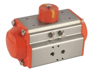
The thrust of the pneumatic piston actuator is relatively large, and it is mainly suitable for the pushing device of large-diameter, high-pressure drop control valve or butterfly valve.
In addition to diaphragm type and piston type, there are also long-stroke actuators. It has a long stroke and a large torque, and is suitable for outputting a rotation angle of 0°~90° and a torque, such as a butterfly valve or a push device for wind.
Pneumatic membrane actuators are available in two forms: positive and negative. When the signal pressure from the controller or valve positioner increases, the valve stem moves downwards is the positive acting actuator. When the signal pressure increases, the valve stem moves upwards is the reaction actuator. The strength of the positive-acting actuator is the access to a thin-film air chamber above the corrugated diaphragm. The signal pressure of the reaction actuator is passed to the membrane air chamber under the corrugated diaphragm. The two can be retrofitted to each other by replacing individual parts.
Actuators can also be divided into spring and springless actuators. Membrane actuators with springs are the most commonly used, and membrane actuators without springs are often used for two-position control.
The output displacement of the spring diaphragm actuator is proportional to the input air pressure signal. When the signal pressure (usually 0.02~0.1MPa) passes into the membrane air chamber, a thrust is generated on the membrane, which moves the valve stem and compresses the spring until the reaction force of the spring is balanced with the thrust, and the push rod is stabilized in a new Location.
The greater the signal pressure, the greater the displacement of the valve stem. The displacement of the valve stem is the linear output displacement of the actuator, also known as the stroke. Stroke specifications are 10mm, 16mm, 25mm, 40mm, 60mm, 100mm, etc.
Control mechanism
The control mechanism, namely the control valve, is actually a throttling element whose local resistance can be changed. The upper part of the valve stem is connected with the actuator, and the lower part is connected with the valve core. As the valve core moves in the valve body, the flow area between the valve core and the valve seat is changed, that is, the resistance coefficient of the valve is changed, and the flow rate of the controlled medium is changed accordingly, so as to achieve the purpose of controlling the process parameters.
