What is an Orbital Motor Working Principle?
An orbital motor, also known as an orbital hydraulic motor, is a special type of internal gear hydraulic motor. The stator of this motor is an internal gear, while the rotor is an external gear, and its tooth profile is cycloidal. The gear center of this motor has an eccentricity. Due to the small number of teeth, the volume of the working space is large, and there are no isolation components for high-pressure and low-pressure oil, making the structure simple, compact, small in size, and light in weight. ATO will introduce the orbital motor, mainly including the following aspects: structural principle, power output, automatic variable, and friction cycloid.
Structure
The structure of the orbital motor mainly consists of a stator and a rotor. The stator is an internal gear, while the rotor is an external gear, and its tooth profile is cycloidal. This design allows the rotor to rotate freely within the stator and generate rotational motion driven by hydraulic oil. In addition, the difference in the number of teeth between the stator and the rotor determines the reduction ratio of the motor, thereby controlling the output speed.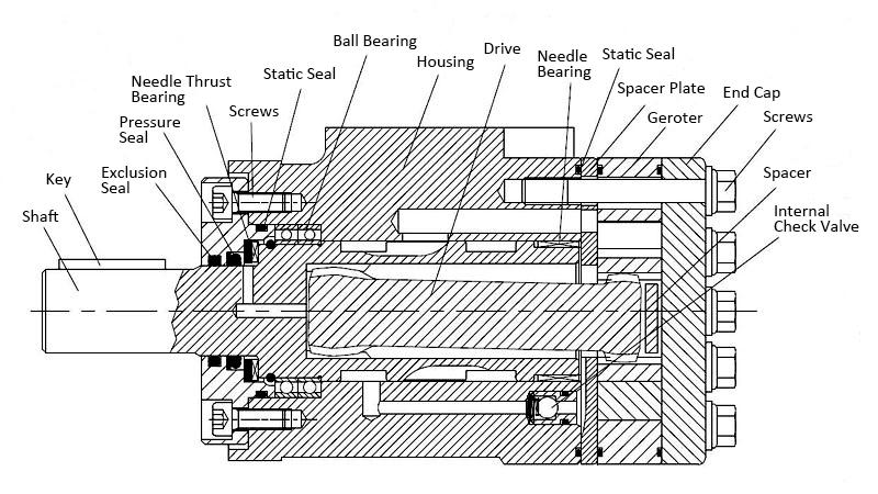
Working Principle
The orbital motor utilizes the geometric properties of the cycloid curve. Convert rotational motion into linear motion. A cycloidal curve is a trajectory that gradually recurses from the center of a circle and can be viewed as consisting of a series of generated small circles. In an orbital motor, the radius of the small circle changes as the angle of rotation changes, causing the shape of the cycloidal curve to change.
Since the movement of the cycloid belt is achieved through cooperation with the gear, the rotation direction of the hydraulic orbital motor is consistent with the movement direction of the cycloid belt. At the same time, since the rotational force of the gear is related to the magnitude of the hydraulic pressure, the speed and rotation direction of the gear can be controlled by adjusting the hydraulic pressure.
Hydraulic force converts liquid energy into mechanical energy, which can be achieved through the cooperation of cycloid belts and gears. Specifically, when hydraulic oil enters the drive shaft, the hydraulic force pushes the drive shaft forward, and at the same time, the cycloid belt between the drive shaft and the sleeve begins to move. A series of gears in the cycloid sleeve match the shape of the cycloid belt. When the cycloid belt moves, it will match these gears. Under the action of hydraulic force, the gears start to rotate. When the gear rotates, it converts the rotational force of the drive shaft into the rotational force of the gear itself, thereby converting liquid energy into mechanical energy. At this time, the drive shaft continues to be pushed by the hydraulic motor force and moves forward continuously, so that the cooperation between the cycloidal belt and the gear is maintained. At the same time, the cycloidal sleeve also begins to move with the drive shaft.
Power output
When hydraulic oil enters the motor from the oil inlet, it pushes the gear on the rotor to generate rotational force. Due to the difference in the number of teeth between the stator and the rotor, the rotor will rotate at a speed lower than the flow rate of the hydraulic oil, thereby achieving a deceleration effect. The rotating rotor transmits power to the external device through the output shaft, driving it to work.
Automatic variables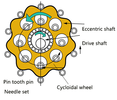
The orbital motor has the characteristics of an automatic variable, that is, its output speed and torque can be automatically adjusted according to changes in the load. When it increases, the rotation speed of the rotor will decrease accordingly, and the flow rate of hydraulic oil will also increase accordingly.
Working process
An orbital motor usually consists of a fixed or moving cycloidal curve and a slider. When the cycloid curve rotates, the slider will make a linear motion as the curve changes. Since the shape of the cycloidal curve is very regular, the speed and acceleration of the slider can be controlled very precisely. This makes orbital motors widely used in many fields, such as robots, automobiles, ships, etc.
The internal slides mate with the star wheel and usually have three or four slides. The slider moves in cooperation with the interior through the shaft, causing the inner and outer cylinders to rotate relative to each other. The crankshaft is connected to the inner slider, so when the inner slider moves, the crankshaft also rotates.
The star wheel operation process usually includes the following steps:
- Liquid flows into the orbital hydraulic motor through the inlet to generate hydraulic pressure.
- The liquid pressure pushes the internal slider to make a circular motion around the star wheel.
- The movement of the inner slider causes the crankshaft connected to other parts to rotate, causing the outer stator to rotate.
- After the stator rotates, the star wheel groove is docked with the slide block, and the energy is transferred to the slide block, allowing it to continue to rotate around the star wheel.
- Hydraulic flow enters and leaves the motor normally, creating pressure or velocity in other components.
Since hydraulic orbital motors are generally designed for low-speed, high-torque applications, their rotational speeds are very low, mostly below 1000rpm. However, to achieve higher power output, high pressure and flow must be provided. Therefore, hydraulic orbital motors are usually used in industrial drives that require high power and slow speed, such as aircraft landing gear, shovels, hydraulic machine tools, etc.
