Air Diaphragm Pump Working Principle
Basic Working Principle
The air operated double diaphragm pump relies on the air compressor to input the compressed air into the air distribution valve of the AODD pump to drive the connecting shaft in the intermediate body of the diaphragm pump to drive the diaphragm pump diaphragm in the medium chamber of the diaphragm pump body to do lateral stretching movement to achieve self-priming fluid. Positive displacement reciprocating pump. In the two symmetrical working chambers of the pump, an elastic diaphragm is installed in each, and the connecting rod integrates the two diaphragms. After the compressed air enters the air distribution valve from the intake joint of the pump, it pushes the diaphragm, which drives the two diaphragms connected by the link to move synchronously. At the same time, the gas in the other working chamber is discharged from the back of the diaphragm to the outside of the pump. The air diaphragm pump is composed of two parts, the air flow structure and the liquid flow structure, which are completely isolated by the diaphragms on both sides.
The air source pressure only needs to be more than two kilograms per square centimeter to work. Under the working pressure of 5 to 8 kg, the high-pressure gas in the valve chamber drives the connecting rod shaft to reciprocate left and right through the airflow dredging system, and at the same time, the consumed low-pressure gas is quickly discharged through the exhaust port. Under the alternating action of high and low pressure gas on both sides, the connecting rod shaft drives the diaphragms on both sides to move left and right, so that the air pressure in the volume chambers on both sides changes alternately, so as to realize the continuous suction and discharge of liquid.
The air distribution mechanism automatically introduces the compressed air into the other working chamber and pushes the diaphragm to move in the opposite direction, thus forming the synchronous reciprocating motion of the two diaphragms. Each working chamber is provided with two one-way ball valves. The reciprocating motion of the diaphragm causes the volume of the working chamber to change, forcing the two one-way ball valves to open and close alternately, thereby continuously sucking and discharging liquid.
As the fluid passes through the diaphragm pump, the soft-seal ball core and valve seat open and close, which makes each outer diaphragm chamber fill and discharge alternately, and the ball core and valve seat respond to the passing pressure difference. And due to the soft sealing form of the ball core and the valve seat, some fluids containing small particles can also be passed.
Working Principle Diagram
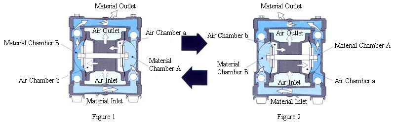
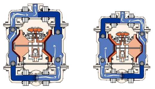
Figure 1: The air is compressed into the back of the air chamber B through the air valve, and the liquid chamber is squeezed by the diaphragm. This air-driven way can relieve the mechanical stress of ordinary piston drive, thereby significantly prolonging the life of the diaphragm. When the compressed air pushes the air chamber B away from the central body, the air chamber A at the other end is simultaneously pulled toward the central body by the connected central shaft. At this time, the air at the back of the air chamber A is discharged to the outside of the pump through the outlet. In this way, the B chamber is formed into a vacuum state, so that the fluid can be pushed from the inlet branch pipe by the external atmospheric pressure to push the valve ball away from the valve seat, so that the fluid can freely enter the B chamber until it is filled.
Figure 2: When the air chamber B squeezed by the air reaches its displacement limit, the air valve will guide the air to the back of the air chamber A, which will also form a squeezing force to push it away from the center body, and at the same time push the connected air chambers B pulls back the center body. At this time, the hydraulic pressure generated by the drive of the air chamber A pushes the inlet valve ball back to the valve seat, and at the same time pushes the outlet valve ball away from the valve seat, so that the fluid can be squeezed and discharged from the pump body from the outlet. The action of the air chamber B being pulled back to the center body makes the A chamber form a vacuum state, so that the fluid can be pushed from the inlet branch pipe to push the valve ball away from the valve seat by the atmospheric pressure and enter the A chamber until it is full.
When the movement of the diaphragm is completed, the air valve guides the air to the back of the air chamber B again, while the air chamber A performs the air discharge action. When the pump returns to the original starting state, the two diaphragms in the pump each complete an air discharge or fluid discharge process. This constitutes a cyclic pumping process. Depending on the conditions of use, the pump achieves self-priming through several complete pump cycles.
