Fuse/CBB65 Capacitor/MOS Tube Testing in Frequency Converter
A frequency converter, also known as an AC power supply/inverter, is a power conversion device. At present, ATO single-phase and three-phase frequency converters are ideal solutions for household appliances, industrial power conversion, laboratory testing, aviation, military applications, etc. ATO.com will introduce you to how to test the fuse/MOS module/CBB65 capacitor in the frequency converter in this article. In order to understand the testing process more clearly, we have released a video explanation, please watch the video for more information.
How to Check a Fuse in a Frequency Converter with a Multimeter?
- Firstly, don’t forget to discharge the converter for 30 min or above, or as an alternative, you can discharge the capacitor via an electrical installation rated at more than 20W, 500 ohms.
- Secondly, test the DC capacitor using a multimeter to see if its voltage is less than 5V DC, if not, make sure it is. Generally, the fuse is located near the absorber plate.
- Finally, put the multimeter in the ohm range and measure the resistance of the fuse, if it is close to 0, it is normal. If the resistance displays infinite, that means the fuse may have been burned.
Related Video
Frequency Converter CBB65 Capacitor Testing
Next, try to do a CBB65 capacitor test. Preparations are the same as for fuse testing. First up, power off the converter and let it discharge for above 30 min, and then make sure that the voltage of the DC capacitor measures less than 5V DC. Finally, disconnect the bridge rectifier and wrap up the heads of the wires in electrical tapes.
Test Steps
- Remove the terminals of either of the two electrodes of the capacitor using a screwdriver or other possible tools.
- Put the multimeter into the capacitance range.
- Detect the capacitance between these two electrodes using the probes. The normal measurement result should be above 20μF.
- Plug the terminals back into the capacitor.
Then, we can try testing an individual capacitor. An example is a capacitor rated at 80μF. When the multimeter shows that the capacitance between the two electrodes is 81μF, it is close to 80μF. It can be said that it is an ordinary AC capacitor.
Related Video
MOS Tube Testing in a Frequency Converter
Finally, we continue with the instructional series on ATO single-phase frequency converters, and try to do a MOS Tube test in a frequency converter.
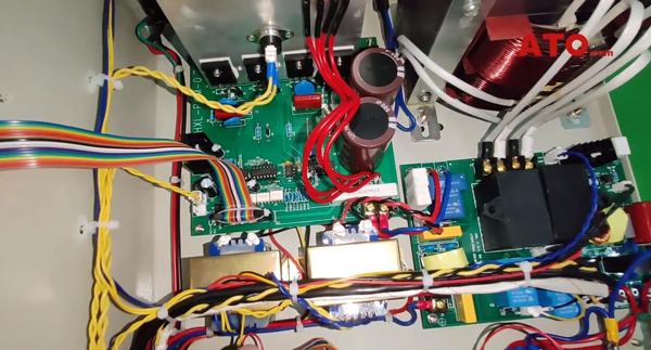
Before testing, let's take a look at the internal structure of the rack-mounted variable frequency power supply. The silver-white component is the aluminum cooling sheet, MOS tubes and the bridge rectifier are directly attached to it for heat dissipation. The board on the right that comes with two black squares is the relay board that is directly connected to the main transformer.
To the left, there are two smaller transformers, and here on the inner side is the display control panel. On the left side is the motherboard of the variable frequency power supply. This is a brief introduction to the internal structure of the rack-mounted variable frequency power supply.
Since its power is relatively small, the rack-mounted frequency converter uses MOS tubes rather than the IGBT module, but both components function in almost the exact same way.
Testing Procedures
- Put the multimeter into the diode mode before measuring the MOS tube. The MOS tube has three pins of which we only need to measure the left and middle ones to measure its voltage.
- Measure and record the voltage of 4 MOS tubes for further discussion with the technician. If the measured voltage falls between 0.4V and 1.8V, the MOS tube is normal.
- As an alternative, you may also measure the tube in the ohm range. If there is resistance between the two pins, usually at the level of kiloohm or milliohm, it means the tube is normal.
Related Video
The above is a detailed description of the fuse/CBB65 capacitor/MOS tube testing. If you want to know more about frequency converters, please visit ATO.com.
