How to Calibrate Accelerometer Sensor?
As we all know, the application of accelerometers in the field of automotive electronics becomes increasingly extensive. In these applications, it is usually necessary to measure the acceleration data based on the vehicle coordinate system, which requires the direction of each sensing axis of the acceleration sensor to be consistent with the vehicle coordinate system.
However, due to the influence of the installation process, there is often a certain deviation between the sensing axis direction of the acceleration sensor and the ideal sensing device during the equipment installation process, so it is necessary to calibrate this installation error. So how does the error arise? What are the methods of calibration? Let's see next in ATO.
Basics and Analysis of Installation Error
When installing a vehicle state measurement device based on a three-axis acceleration sensor, the most ideal installation state is to make the three sensing axes of the three-axis acceleration sensor parallel to the three axes of the vehicle coordinate system, and the measured and recorded data are closest to the vehicle real driving conditions.
The coordinate system of the three-axis accelerometer sensor has been calibrated at the factory, and its 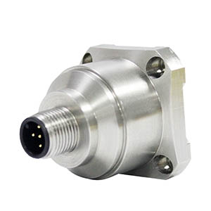 three axes are considered to be orthogonal to each other. After the actual installation is completed, it is impossible to ensure that the three axes of the sensor coordinate system are completely parallel to the three axes of the vehicle coordinate system, and the deviation between the two coordinate systems is defined as the installation error.
In addition, acceleration sensors have very high requirements for sensitivity. In fact, no matter what type of sensor, the sensitivity is very important. The higher the sensitivity, the greater the information-to-noise ratio of the measurement system, and the system is less susceptible to electrostatic interference and electromagnetic fields.
However, under long-term use, the sensitivity of the sensors will have a certain deviation. In addition, errors will also occur in these two cases: the insulation resistance of the sensitive core of the acceleration sensor decreases, resulting in the attenuation of the piezoelectric coefficient of the sensitive core and the excessive temperature response coefficient of the piezoelectric material in a non-room temperature environment too big. At this time, we need to calibrate the acceleration sensor to reduce the error.
So after knowing the formation of the error, we have 3 ways to align the acceleration sensor. Each calibration method has its suitable range and principle, and we need to decide the type of method to use according to the actual situation.
Calibration Method
Gravity Field Method
For zero-frequency response accelerometers, the geostatic gravity field method can be used for calibration. The gravitational field method is also a high-precision absolute calibration method.
The sensor to be calibrated is mounted on a table, which can be rotated around the central axis, and the sensitive axis of the sensor also rotates with it. You should pay attention to it when using this method:
- In its principle, this method belongs to static absolute calibration, and is only suitable to types of accelerometer sensors (such as servo type, piezoresistive type, strain type, tension wire, etc.) with zero frequency response.
- The equipment must have a good vibration isolation foundation, and the rotating shaft should be strictly in a horizontal position, otherwise the accuracy will be affected.
Turntable Gravity Field Calibration Method
Zero frequency calibration is a static calibration. Appropriate improvements should be made to the zero-frequency calibration device, that is to say, the workbench rotates at a constant speed at a certain frequency to form a low-frequency gravity field calibration platform. When the table rotates, the sensitive element of the acceleration sensor will be affected by the acceleration of -1~1g, and the output value and dynamic sensitivity of the acceleration sensor at different frequencies can be recorded. This method is only suitable for low frequency accelerometers.
Comparative Method
The comparison method is the most commonly used method for sensor calibration. It is simple principle and easy to operate. Two accelerometers are mounted back-to-back (or on a rigid support), one of which is a specific reference standard accelerometer whose sensitivity and all technical properties are known. The other is the sensors to be calibrated, energizing them with the same acceleration.
The same principle applies to calibrating velocity and displacement sensors.
Standard Accelerometer - Standard sensor is the most critical link in comparison and calibration. Its quality has a very important influence on the calibration result. Therefore, certain requirements or regulations need to be made for standard sensors. Our country has promulgated standard piezoelectric accelerometer verification procedures. From the perspective of its role as a vibration reference for the transfer value in the comparison method, the following requirements should be met:
- High sensitivity, calibrated by laser method or reciprocal method, and the calibration accuracy is better than 0.5%.
- The sensitivity should have long-term stability, that is to say, there should be no significant change during the inspection period, and it should be higher than 1 times the calibration accuracy.
- The lateral sensitivity ratio is not more than 3%, and the linearity is higher.
- The non-vibration environment sensitivity should be low, such as temperature response, magnetic sensitivity, substrate strain sensitivity, and transient temperature sensitivity should be as low as possible.
