How to Control a BLDC Motor Via RS485 and CAN Communication?
In modern industrial and automation systems, precision motor control is essential. One highly effective method for achieving this is through the use of RS-485 and CAN bus communication protocols. In this guide, we'll walk you through setting up a BLDC (Brushless DC) motor control system using both RS-485 and CAN interfaces to enable accurate, real-time speed and direction control.
Required Components
Before setup, make sure you have the following components prepared:
- BLDC motor
- BLDC Motor Controller
- 24V DC switching power supply
- USB to RS-485 converter
- USB-CAN analyzer
- PC with BLDC Control Software
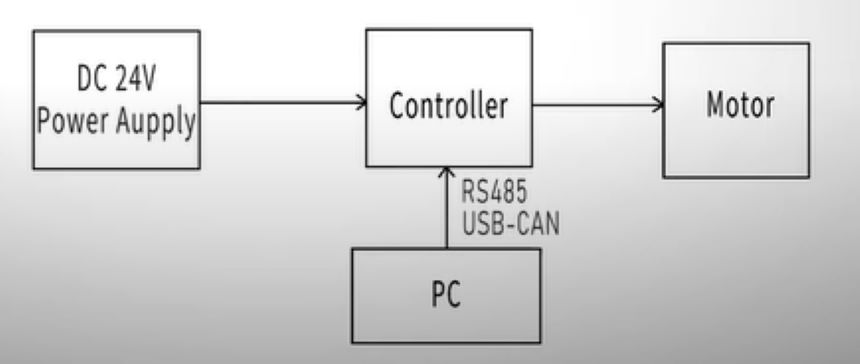
Among these components, the BLDC motor serves as the core driving unit, while the controller functions as the command executor, responsible for interpreting and executing speed and direction instructions. The 24V DC switching power supply provides stable energy to both the motor and controller. The USB to RS-485 converter and USB-CAN analyzer serve as communication bridges, facilitating reliable data exchange between the controller and the PC. The PC, equipped with dedicated BLDC control software, sends commands over RS-485 or CAN to achieve precise and real-time motor control. Ensure that all hardware is compatible with your system. If unsure, feel free to visit our website and consult our technical experts for specification details.
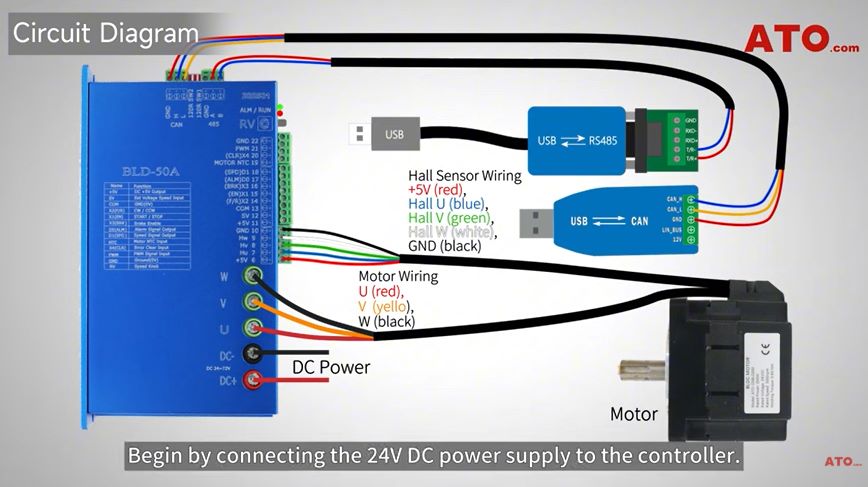
Circuit Diagram
Now, let's wire up the system correctly as per the wiring diagram provided. Begin by connecting the 24V DC output from the power supply to the controller, making sure the polarity is correct to prevent any damage. Then, attach the motor's U, V, and W wires to the controller's output terminals. If your motor includes a Hall sensor, connect it to the designated Hall input terminals to enable accurate position feedback. For communication, use the RS-485 converter to link the controller's RS-485 port to your PC, and similarly, connect the CAN analyzer to the controller's CAN port for dual communication capability. Once all components are connected, cross-check the entire setup with the wiring diagram to confirm that the circuit is correctly configured and ready for operation.
Controller Preparation
Before sending commands, you need to adjust the controller settings to ensure it operates under software control. Start by disabling the RV terminal, which functions as the input for manual potentiometer control. Since speed control will be managed through RS-485 communication, this step is essential. Next, set both DIP switches SW1 and SW2 to OFF. This configuration allows the controller to accept instructions solely through software communication, instead of relying on manual input.
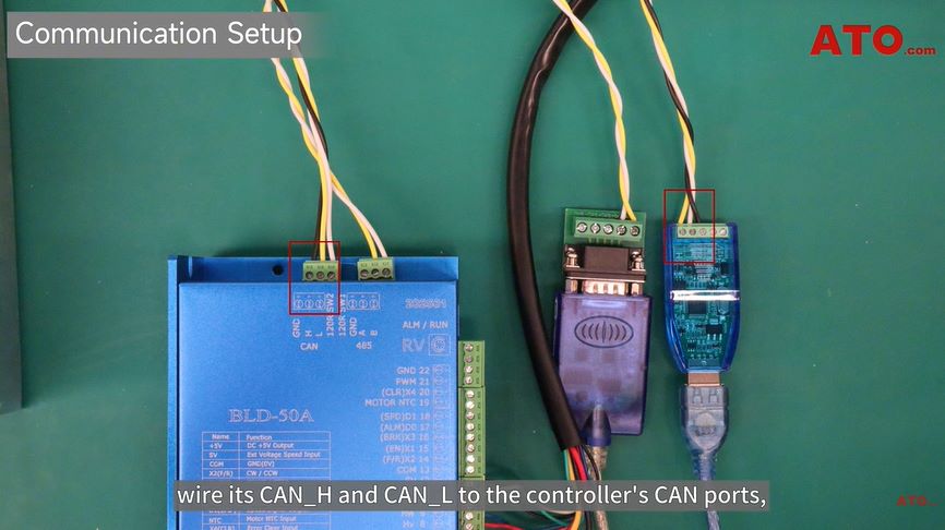
RS485 & CAN Communication Setup
To establish communication between the sensor and the controller, first verify the device's CAN and RS-485 interfaces. For CAN communication, connect the sensor's CAN_H and CAN_L wires to the matching CAN port on the controller. For RS-485 communication, connect the A and B wires to the corresponding RS-485 terminals on the controller. Once all wiring is properly connected, Power on the system and then connect the sensor and controller via USB to a PC for configuration or data monitoring. This setup ensures that the communication link between the devices is stable and available at all times.
Software Setup
To set up your BLDC motor controller, begin by launching the dedicated BLDC control software on your PC. Navigate to the "COM Setting" section and click "Connect" to initiate communication. If successful, the software will automatically read the motor parameters, confirming that the controller is properly connected. If the connection fails, ensure the controller address is set to the default value of 01 and the baud rate is 38400. Additionally, verify the correct COM port in your PC's Device Manager under Ports (COM & LPT). Once connected, proceed to the "Parameter Setting" section and set PN14 and PN15 to 3. This configuration enables CANBUS to function as both the data and control input, allowing the controller to operate reliably within a CAN communication system.
Parameter Setting
To configure the controller for dual communication input, open the software and navigate to the Parameter Setting section. Set PN14 = 3 and PN15 = 3. Here, PN14 defines the data channel and PN15 the control channel. Setting both to 3 enables the CANBUS interface to handle both command and data traffic.
With this configuration in place, your BLDC controller becomes capable of interpreting control instructions from both RS-485 and CAN communication sources. This dual-input mode enhances system flexibility and ensures smooth signal routing from multiple interfaces.
For instance, to rotate the motor in reverse at 3000 RPM, you'll send a target data value of 0x8BB8. In this hexadecimal data, the direction bits are set to 10, indicating reverse motion, and the remaining bits encode the desired speed. Byte 6 in your message must differ from the previous command to trigger the action. You must also recalculate and update Byte 7 and Byte 8 with the correct checksum derived from Bytes 1 through 6.
To stop the motor, simply transmit a target data of 0x0000 and set the direction bits to 00. Similarly, to achieve a forward rotation at 500 RPM, use the target data 0x41F4, with direction bits set to 01. As with every new command, ensure a new Byte 6 value and correct checksum update.
Throughout this process, you can monitor motor feedback via CAN messages, which provide information such as bus voltage, bus current, temperature, and real-time speed. The status frames typically appear with a Frame ID such as 0x18700055 and contain all the vital statistics needed for real-time monitoring and diagnostics.
Conclusion
This guide provides a complete yet beginner-friendly walkthrough of how to set up and control a BLDC motor using both RS-485 and CAN communication protocols. Whether you're developing an industrial solution or prototyping a robotics project, following these steps ensures reliable performance and a deeper understanding of motor communication control. If you have any questions, you can watch the video below.
