How to Build a BLDC Motor Controller Circuit Using I/O + SV?
The I/O + SV method can efficiently control the speed and direction of the BLDC motor. This method controls the start and stop and direction of the motor through input signals, and adjusts the speed through variable voltage. In this guide, ATO online store will guide you on how to create a BLDC (brushless DC) motor controller circuit using the input/output (I/O) + speed voltage (SV) control method.
Basics of Control
Before we dive into the circuit design, let’s first understand how the I/O + SV approach works in BLDC motor control
Input/Output (I/O) Signals
These signals are used to enable or disable the motor, change its direction, and provide basic control functions. In our setup, a rocker switch will be used to control these I/O signals.
Speed Voltage (SV)
"SV" refers to the dedicated input pin on the motor driver that allows you to adjust the motor’s speed using an external potentiometer or analog signal. The potentiometer acts as a rheostat, adjusting the variable resistance to produce a changing voltage. This voltage is then sent to the BLDC driver’s SV pin, which adjusts the motor's speed based on the voltage level.
By combining these two methods—I/O for control and SV for speed adjustment—the I/O + SV control method provides a versatile and efficient way to manage the motor's operation.
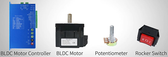
Components Needed
To build your BLDC motor controller circuit, gather the following components:
- BLDC Motor
- BLDC Motor Driver
- Potentiometer
- Rocker Switch
- 24V DC Power Supply
These components will form the foundation of your motor control circuit.
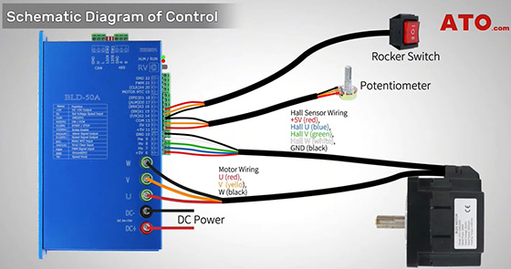
Schematic Diagram of Control
Now, let’s move to the wiring.
- Power Supply: Connect the positive and negative terminals of your power supply to the respective power input pins on the motor driver.
- Motor Phases: Connect the three motor phases (U, V, W) from the driver to the respective terminals of the BLDC motor.
- Hall Sensor Signals (if available): If your BLDC motor has Hall sensors for accurate commutation, connect the Hall sensor signals to the Hall sensor input pins on the motor driver.
- Potentiometer: Connect one end of the rotary potentiometer to the +5V power supply and the other end to ground (COM). The wiper (the adjustable middle pin) should be connected to the SV pin on the driver.
- Rocker Switch: Connect one side of the rocker switch to X1(EN) on the driver (for motor on/off), and the other side to X2 (F/R) (for direction change), with the ground wire to COM.
Hardware Settings
Before testing the circuit, some settings need to be adjusted on the motor driver: Disable the RV (Reference Voltage) function on the driver by turning the RV adjustment screw counterclockwise until fully off. And set switches SW1 and SW2 to the OFF position, as per the driver’s instructions.
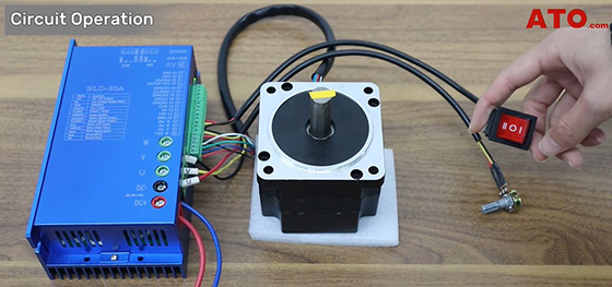
Full Circuit Setup
Once everything is connected, you should have a complete BLDC motor controller circuit ready for operation.
The rocker switch is used to control the motor's start/stop and direction. In the position II (ON) of the rocker switch, the connection between COM and X1 will start the motor. You can verify this connection by checking continuity with a multimeter. The indicator light on the driver should also confirm the motor is powered on. In position I, the rocker switch will connect COM and X2, changing the direction of the motor. The potentiometer controls the motor's speed by adjusting the voltage sent to the SV pin on the driver.
Circuit Operation
To operate the circuit:
- Motor Enable: Toggle the rocker switch to position II to enable the motor.
- Adjust Speed: Use the potentiometer to adjust the motor speed. Rotating it changes the voltage level at the SV pin, which in turn controls the speed of the motor.
- Stop the Motor: Switch the rocker to position O to stop the motor.
- Change Direction: Toggle the rocker switch to position I to reverse the motor’s direction while still controlling the speed with the potentiometer.
This guide has walked you through how to build a BLDC motor controller circuit using the I/O + SV approach. By combining simple control signals (I/O) and an adjustable speed input (SV), you can easily manage both the speed and direction of your BLDC motor in a variety of applications. If you have any questions, you can watch the video below.
