How to Build a BLDC Motor Controller Circuit Using I/O + RV?
In the previous article, we explored how to control a BLDC (Brushless DC) motor using the I/O+SV control method. In this article, we will introduce another efficient approach: I/O+RV control.
What is 'I/O+RV' Control?
The I/O+RV control method is a hybrid approach that combines digital control and analog control to achieve efficient BLDC motor operation. It primarily utilizes two key signals:
First, the I/O (Input/Output) signal is used for motor start/stop and direction control, typically operated via a rocker switch. By toggling the rocker switch to different positions, specific commands are sent to the BLDC controller to start, stop, or reverse the motor.
Second, the RV (Reference Voltage) signal is an analog input that allows smooth motor speed control by adjusting the input voltage. Many BLDC controllers come with a built-in potentiometer connected to the RV terminal. By rotating the potentiometer, users can modify the voltage level at the RV input, achieving precise and continuous speed regulation.
By integrating digital control via the rocker switch and analog speed adjustment via the RV terminal, the I/O+RV control method offers a flexible and efficient way to manage BLDC motors without requiring complex programming. This makes it ideal for applications that demand stable and adjustable speed control.
Required Components
To build this control circuit, you will need the following components:
- BLDC motor controller
- BLDC motor
- Rocker switch
- 24V DC power supply
- Wiring, multimeter, and basic tools
Before purchasing, make sure that all components are compatible with your system’s voltage and current requirements to avoid incompatibility issues.
Circuit Wiring
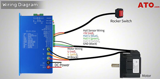
Connecting the Power Supply: Start by connecting the 24V DC power supply to the BLDC controller’s DC input terminals to ensure a stable power source.
Connecting the Motor: Next, connect the three motor phase wires (U, V, W) to the corresponding terminals on the BLDC driver. If your BLDC motor includes Hall sensors, connect them to the appropriate pins on the BLDC controller for precise electronic commutation.
Connecting the Rocker Switch: The rocker switch is responsible for controlling the motor’s start/stop function and direction. It usually has three terminals: COM, X1, X2. Ensure that you connect these terminals correctly according to the wiring diagram to enable smooth operation of the rocker switch.
Configuring the Controller: If you plan to adjust the motor speed using the built-in RV potentiometer, make sure to turn off SW1 and SW2 on the BLDC controller. This ensures that the internal speed control is active.
Circuit Testing and Verification
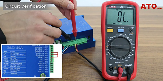
As explained earlier, the rocker switch is used to control the enable and direction functions.
- Switching to position II connects COM to X1 (EN), starting the motor. Testing continuity between these two terminals with a multimeter shows the connection is complete.
- Switching to position I, while keeping X1 (EN) connected, connects X2 (F/R) to COM, reversing the motor direction. Measuring continuity between X2 and COM shows these two terminals are also connected.
Once the motor is enabled, you can adjust its speed using the built-in RV potentiometer on the BLDC controller.
- Rotate the RV knob CW to increase the motor speed.
- Rotate it CCW to decrease the speed until the motor stops.
The RV terminal allows precise analog speed control, enabling smooth speed variations without needing external controllers or complex programming.
Circuit in Action
After completing the wiring, the I/O+RV control system functions as follows:
- Toggle the rocker switch to Position II, and the motor starts running forward.
- Use the RV potentiometer to adjust the motor speed smoothly.
- Toggle the switch to Position O, and the motor stops immediately.
- Toggle the switch to Position I, and the motor runs in reverse.
- Use the RV potentiometer again to control speed in reverse mode.
Summary of Rocker Switch Positions
|
Switch Position |
Function |
Motor State |
|
Position II (Forward Direction) |
COM connected to X1 (EN) |
Motor ON |
|
Position O |
All terminals disconnected |
Motor OFF |
|
Position I (Reverse Direction) |
COM connected to X2 (F/R) |
Motor ON |
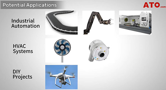
Applications of the I/O+RV Control Method
The I/O+RV control method is widely used in industrial and DIY projects due to its ease of operation and precise speed control. Some common applications include:
- Industrial Automation: Conveyor belts, robotic arms, and CNC machines.
- HVAC Systems: Fans and blowers with variable speed and reversible airflow.
- DIY Projects: Drones, electric vehicles, and more.
Whether for industrial applications or personal projects, this control method offers excellent performance and flexibility.
If you're planning to build a BLDC motor control circuit, visit ATO.com to explore a wide range of BLDC motors, controllers, power supplies, and tools. Whether you're a professional engineer or a DIY enthusiast, ATO provides everything you need to bring your automation projects to life. For more details, you can click on the video below to watch.
