How to Install a Potential Transformer?
Potential transformers are an important part of the power system, used to measure and monitor voltage signals to ensure the safe and stable operation of the power system. Installing a potential transformer is a critical process that requires following several important precautions, and it is also important to understand troubleshooting methods to ensure its proper operation. The following are installation considerations and troubleshooting guidelines for voltage transformers.
Installation Steps
- Site Selection: Voltage transformers are generally installed in complete sets of distribution cabinets or directly on the concrete platform. The concrete platform should be dry and reach a certain strength before installing the voltage transformer. Before installation, the voltage transformer itself should be carefully inspected and qualified. The potential transformer's secondary side is strictly prohibited from short circuits.
- Insulation Inspection: Before installation, carefully inspect the voltage transformer's insulation materials and insulation system to ensure that they are not damaged or contaminated. The insulation should be kept dry and clean.
- Bracket Installation: Install the potential transformer bracket or base, making sure that the bracket is secure and able to support the weight of the transformer. Use bolts or anchors to secure the bracket as needed.
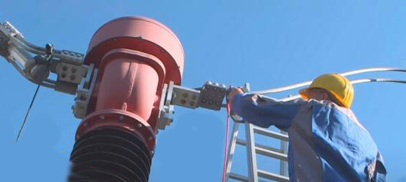
- Cable Connection: Connect the main coil of the potential transformer to a high-voltage supply or cable. Ensure that the connection is secure and that the cable is not subjected to tension or bending.
- Secondary Coil Connection: Connect the secondary coil of the voltage transformer to a measuring device such as a relay, meter, or data acquisition system. Ensure that the connections are correct and error-free.
- Insulation Test: Perform an insulation test before start-up to ensure that the insulation of the voltage transformer meets the standard requirements. Use insulation test instruments to test the voltage transformer's case and insulation materials.
- Adjustment and Calibration: After installation, carry out the necessary calibration and alignment of the voltage transformer to ensure the accuracy of the measurement results. This usually requires specialized equipment and knowledge.
- Ground Connection: If the potential transformer needs to be grounded, make sure the ground wire is connected to the appropriate location on the voltage transformer to ensure safe operation.
- Enclosure and Protection: After the installation is complete, ensure that the voltage transformer's enclosure and insulation are adequately protected against contamination and corrosion from the external environment.
- Records and Documentation: Record details of the installation process, including connection diagrams, calibration values, and insulation test results. These records will assist in future maintenance and troubleshooting of the voltage transformer.
Wiring Methods
Single-phase Wiring: Which can be used to measure the line voltage of 35kV and below the neutral point not directly grounded system or the relative ground voltage of 110kV and above the neutral point grounded system.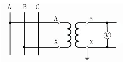
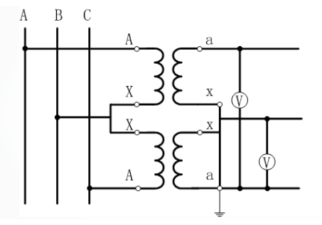
V/V Wiring: V/V wiring is the two fully insulated single-phase potential transformer high and low voltage windings are connected to the phase and the phase constitute an incomplete triangle. This method is commonly used in the neutral point is not grounded or through the arc-canceling coil grounded 35kV and below in the high-voltage three-phase system, especially a 42kV three-phase VT system.
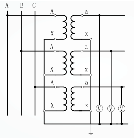
YN, yn, d0 or YN, y Wiring: Three single-phase three-winding voltage transformers are used to form YN, yn, d0 or YN, y wiring, d0, which are widely used in 3~220kV systems, and their secondary windings are used to measure the phase-to-phase voltage and phase-to-ground voltage, and the auxiliary secondary windings are connected to open triangles for accessing the AC power grid insulation monitoring instruments and relays.
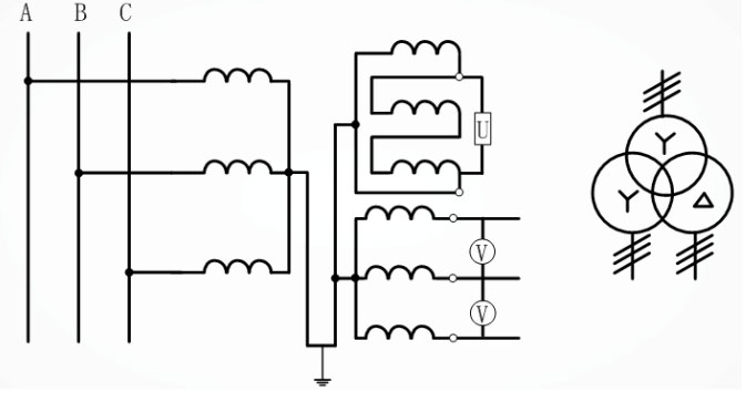
Y0/Y0/Δ Wiring: Three single-phase three-winding potential transformers or one three-phase five-column three-winding voltage transformer are connected into Y0/Y0/Δ type.
Precautions
VT should be tested and inspected by the regulations before being put into operation. For example, measuring polarity, connecting groups, shaking insulation, checking the phase sequence, etc..
PT wiring should ensure its correctness, the primary winding and the measured circuit should be connected in parallel, the secondary winding should be connected in parallel with the connected measuring instruments, relay protection devices, or the voltage coil of the automatic device, and at the same time, pay attention to the correctness of the polarity.
Connected to the secondary side of the potential transformer load capacity should be appropriate, connected to the secondary side of the voltage transformer load should not exceed its rated capacity, otherwise, it will make the transformer error increase, it is difficult to achieve the correctness of the measurement.
Voltage transformer secondary side is not allowed to short circuit. Because the potential transformer impedance is very small, if the secondary circuit is short-circuited, there will be a very large current, which will damage the secondary equipment and even jeopardize personal safety. A voltage transformer can be installed on the secondary side of the fuse to protect itself from damage due to a short circuit on the secondary side. If possible, the primary side should also be equipped with fuses to protect the high-voltage power grid from high-voltage transformer winding or lead failure to jeopardize the safety of the primary system.
To ensure the safety of people in contact with measuring instruments and relays, the secondary winding of the VT must have a point of grounding. This is because grounding prevents the PT and relays from being exposed to high voltages that jeopardize personal safety when the insulation between the primary and secondary windings is damaged.
The secondary side of the potential transformer should never be allowed to short-circuit. The voltage transformer itself is a very small impedance, once the vice side of the short circuit, the current will grow dramatically and burn the coil. For this reason, the primary side of the potential transformer is connected to a fuse, the secondary side of the reliable grounding, to avoid the primary and secondary insulation damage, and the secondary side of the high potential to ground and cause personal and equipment accidents.
Abnormalities and Treatment
Common Abnormalities
- Three-phase Voltage Indication Imbalance: One phase is reduced (can be zero), the other two phases are normal, the line voltage is abnormal, or accompanied by acoustic and optical signals, maybe the transformer high-voltage or low-voltage fuse melting.
- The Neutral Point of the Ineffective Grounding System is a Three-phase Voltage Indication Imbalance: One-phase lower (can be zero), the other two-phase elevated (up to line voltage) or pointer swing, maybe a single-phase grounding fault or fundamental frequency resonance, such as the three-phase voltage at the same time, and more than the line voltage (the pointer can be swung to the head), it may be a split-frequency or high-frequency resonance.
- High-voltage fuse has blown several times, it may cause serious damage to the internal insulation, such as winding layer-to-layer or turn-to-turn short circuit fault.
- A neutral point effectively grinds the system, bus reversing operation, phase voltage rise, and swing at low frequency, generally a series resonance phenomenon; if there is no operation, suddenly phase voltage abnormally high or low, maybe the transformer internal insulation damage, such as insulation bracket winding, winding layer-to-layer or turn-to-turn short-circuit failure.
- The neutral point effectively grounded the system, and the potential transformer is put into operation when the voltmeter indication is not stable, maybe the high-voltage winding N (X) end grounding contact is poor.
- Voltage transformer circuit disconnection processing.
Processing Method
- According to the relevant provisions of relay protection and automatic device, exit the relevant protection to prevent false operation.
- Check whether the high and low voltage fuse and automatic air switch are normal, such as the fuse is blown, should find out the reason for immediate replacement, and when the fuse is blown again, it should be handled carefully.
- Check the VT voltage circuit all the joints have no loose, or disconnection phenomenon, switching circuit has no poor contact phenomenon.
Installation and maintenance of potential transformers are essential to ensure the reliability and safety of the power system. Following the above precautions and troubleshooting guidelines will help ensure that the voltage transformer operates properly and provides accurate voltage measurements. In the case of complex faults, it is recommended to seek professional technical support to ensure that the problem is solved. ATO shop has professional engineers who can answer your questions, if you encounter any problems, welcome to click on the inquiry, we are happy to serve you.
