How Does the Potential Transformer Work?
Potential transformers are an important instrument in electrical engineering used to measure voltage signals and convert high voltages to low voltages to measure, monitor, and control voltages in power systems. Their principle of operation is based on the method of electromagnetic induction, and the ATO online shop will detail how voltage transformers carry out their work.
A potential transformer is also known as an instrument transformer (PT). It is an instrument that changes a high voltage into a low voltage and maintains a certain relationship with the original in phase. Its working principle, construction, and wiring are the same as the transformer, only the capacity is smaller, usually only a few tens or hundreds of volt-amperes. Its purpose is to reduce the high voltage by a certain proportion so that the low voltage coil can accurately reflect the change of the high voltage quantity value, to solve the difficulties of high voltage measurement. At the same time, as the PT reliably isolates the high voltage, thus ensuring the safety of the measuring personnel and protection device.
Main Components
- Main Coil: The main coil usually encloses the voltage signal to be measured. It is a coil wound on a magnetic core and covered by an insulating material to protect the wires and provide insulation. The number of turns the primary coil is wound and the characteristics of the coil material determine the rated voltage and characteristics of the transformer.
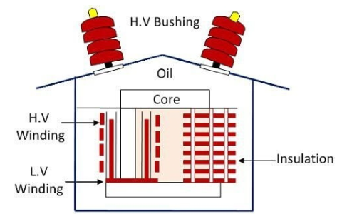
- Secondary Coil: The secondary coil is usually located around the primary coil and consists of a coil wound on a magnetic core. It is electromagnetically coupled to the primary coil and induces a secondary current by electromagnetic induction. The number of turns in the secondary coil determines the transformation ratio of the voltage transformer.
- Magetic Core: A magnetic core is usually located between the primary and secondary coils and is used to enhance the electromagnetic induction effect. The core is usually made of ferrous material to improve the efficiency of magnetic field transmission and induction.
- External Insulation and Enclosure: VT usually provided with external insulation and enclosure to ensure safe operation and to prevent electric shock and insulation failure.
Principle of Operation
The principle of operation of voltage transformers is based on Faraday's law of electromagnetic induction, which can be briefly summarized as follows: when a magnetic field passes through a coil (the main coil), a certain electromotive force is induced in the coil. The potential transformer itself has a very low impedance so that in the event of a short circuit on the secondary side, the current will increase dramatically and burn the coil. For this reason, the primary side of the voltage transformer is connected to a fuse, and the secondary side is reliably grounded, to avoid the primary and secondary insulation damage, the secondary side of a high potential to ground and cause personal and equipment accidents.
Voltage transformers contain a primary coil and a secondary coil. When a current is passed through the primary coil, a varying magnetic field is generated. This magnetic field passes through the secondary coil and induces a voltage. According to Faraday's law of electromagnetic induction, the secondary voltage is proportional to the current in the primary coil. By adjusting the number of turns in the secondary coil, the magnitude of the secondary voltage can be varied, allowing the voltage to be transformed and measured. This principle enables voltage transformers to convert high voltages to low voltages to safely measure and monitor voltage signals in power systems.
Working Process
Voltage Input: The main coil of the potential transformer introduces the voltage signal to be measured, usually through a connector or cable. Measurement of voltage transformers are generally made into a single-phase double-coil structure, the voltage transformer primary voltage for the voltage to be measured (such as power system line voltage), can be used in a single-phase VT but also can be used with two units connected to the V-V shape for three-phase PT use.
Electromagnetic Induction: When a voltage signal passes through the primary coil, current flows through the coil, producing a changing magnetic field. This magnetic field passes through the secondary coil and, according to Faraday's law of electromagnetic induction, induces an electromotive force (voltage) in the secondary coil. During normal operation, the three-phase voltages of the power system are symmetrical, and the sum of the three-phase VT induced electromotive forces on the third coil is zero. Once single-phase grounding occurs, the neutral point is displaced, and a zero-sequence voltage occurs between the terminals of the open delta to cause the relay to operate, thus protecting the power system.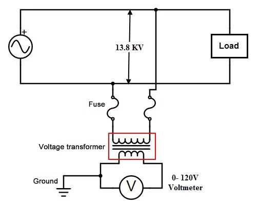
Secondary Voltage Output: The induced secondary voltage output is usually a constant proportion of the primary voltage. This ratio is determined by the number of turns in the secondary coil and is called the transformer ratio of the voltage transformer. The presence of a zero-sequence voltage in the coil results in a zero-sequence flux in the corresponding core. For this reason, such three-phase voltage transformers are used with a side yoke core (for 10 kV and below) or with three single-phase voltage transformers. For this type of transformer, the accuracy of the third coil is not required to be high, but a certain degree of overexcitation characteristics (i.e., when the primary voltage increases, the magnetic flux density in the core also increases by a corresponding multiple without damage).
Signal Processing: The secondary voltage can be passed through the connector to the measuring equipment or control system for signal processing. Usually, the secondary voltage needs to be adjusted and calibrated in some way to obtain an accurate voltage measurement.
Key Points in the Working Process
- Insulation: To ensure safety and prevent the risk of electric shock, the primary and secondary coils of a voltage transformer must be well insulated, usually using insulating materials and housings.
- Transformer Ratio: The transformer ratio (ratio of secondary to primary voltage) of a voltage transformer is usually fixed and is selected according to the requirements of the application. The ratio affects the size of the output signal.
- Linear Characteristics: Voltage transformers are usually designed to have linear output characteristics, i.e. the output voltage is proportional to the input voltage. This makes voltage transformer measurements easier to interpret and process.
- Accuracy: Voltage transformers typically have a high degree of measurement accuracy, but require calibration and maintenance as required by the application to ensure accuracy.
Voltage transformers are important electrical measurement devices that utilize electromagnetic induction to convert high voltages to low voltages to measure and monitor voltage signals in power systems. With proper design and maintenance, potential transformers can provide accurate, safe, and reliable voltage measurements that are critical to the operation and maintenance of power systems.
