How to Use a 24V DC Gear Motor?
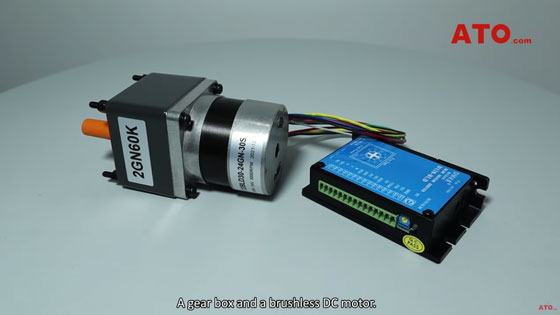
A DC gear motor is a type of electric machine that includes two key components: A gear box and a brushless DC motor.
The addition of a gear head to a DC motor reduces the speed while increasing the torque output.
For this reason, gear motors are most often used in applications that require a lot of force as well as highly precise velocity control to move heavy objects.
Such applications include compressors, pumps, electrically-driven doors, robotic arms and other equipment.
ATO offers a diverse range of spur gear motors, planetary gear motors and worm gear motors with power options falling between 30W and 2000W, voltage between 12V and 48V DC, torque between 0.1Nm and 300Nm, providing you with highly efficient gear motor solutions that can meet any application requirements.
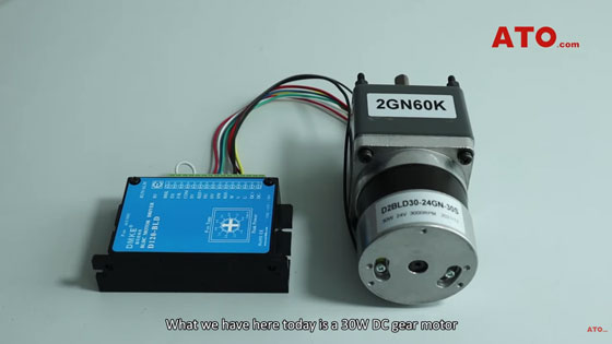
What we have here today is a 30W DC gear motor that operates at 24V and 1 to 60 gear ratio.
24V DC gear motor wiring precautions
Let’s break down the whole wiring system.
Apart from a gear reducer and a DC electrical motor, there’re two sets of lines: 5 hall lines and 3 power lines that go from the DC motor and are to be connected to the BLDC motor controller.
As to the controller, it has an in-built design for speed control and serial ports including those for Brake, enable, Forward/Reverse Switch, Speed Control by external potentiometer, and these five serial ports are for hall lines, and these three for power lines and these two for power supply.
You can connect the motor to the controller through wiring terminal.
The rated speed of the BLDC motor is 3000 rpm which is reduced by the combined gear box at a gear ratio of 1 to 60, and thus the resulting output speed is 50 rpm.
Moving on, we’ll tell you the wiring precautions.
The intended use of each hall line is explained as follows the red and black lines shall be connected to REF positive and negative poles, and blue line to HU, green to HV and white to HW.
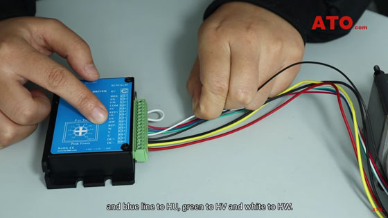
As to power lines, red one to U, yellow to V and black to W.
Only when the Enable port is connected to the COM will the driver be able to work. Otherwise, the motor stops spinning when EN is disconnected from COM.
The positive and negative electrodes of DC are supposed to be connected to 0V (the COM power supply) and 24V.
The SV port for external speed control is optional for connection as required.
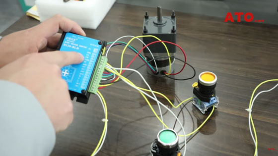
Turn the built-in screw hole using a little screwdriver to control the speed, and you can see the output shaft starts to rotate. Adjust the speed to the maximum, it can be seen clearly that the shaft rotates at a relatively lower speed.
We also have a Forward/Reverse push button connected to the electric circuit. Switch off the EN button, press the F/R button, then restart the EN button, and you can see the output shaft reverses rotation.
Pay attention here. It’s advised to stop the EN switch before switching the F/R button, or else the gear motor will produce significant vibration, though the intended purpose is achieved.
Want to know more about the video view:
At ATO, we also have a highly skilled team of motor experts who can help you understand your power transmission options. Whether you need the right motor to connect to your existing gear train or need help creating the optimal gear motor for various applications, we can help. Contact us today through the link in the description below if you’re in need of high-quality geared motor solutions.
