Hydraulic Punch Working Principle
A hydraulic punching machine is a kind of equipment used for punching holes in various metal sheets, pipes, and profiles. It has the characteristics of simple operation, convenience, high efficiency, and low cost, and is widely used in the machining industry. Let me explain to you how the hydraulic punching machine works and other knowledge about the hydraulic punching machine.
Main components of CNC hydraulic punching machine
Bed part: the bed and workbench are cast iron parts.
Clutch: When the press is not working, the cam of the manipulator blocks the tail of the turning key, so that the crescent wheel of the working part is completely inserted into the semicircular groove of the crankshaft. At this time, the crankshaft is idling, and the slider stops at the top dead center; when the press is working, the cam of the manipulator rotates an angle, causing the tail of the opened steering key to rotate 45° under the action of the spring, and the rear of the working part enters the three rings, the middle sleeve of any one of the slots. The clutch is in the combined position, and the flywheel drives the crankshaft to rotate, and then the slider moves up and down.
Slider: There is a presser foot-type safety device under the spherical bowl inside the slider, which is in contact with the ball head of the adjusting screw to ensure that the press is not damaged when it is overloaded. Open the front square cover to replace the safety device.
Brake band: An eccentric brake band is installed at the left end of the crankshaft. When the clutch is disengaged, it can overcome the inertia of the reciprocating motion of the slider to ensure that the crankshaft stops at the top dead center.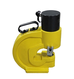
Manipulator: When using a manipulator, the mechanism that controls the engagement and disengagement of the clutch. Switch the connection position of the joystick of the manipulator to realize two actions of single stroke and continuous stroke.
CNC hydraulic punching machine installation
After the hydraulic punch is leveled, an anchor bolt is installed and concrete is backfilled. After the concrete is completely solidified, tighten the anchor bolts and nuts evenly, and then use a level to recalibrate the level of the workbench. The ground wire should be properly connected. The hydraulic punch must be completely solidified before it can start working.
After the hydraulic punch is installed, wash the anti-rust grease on the surface of the hydraulic punch with kerosene. When cleaning, be careful not to damage the painted surface. At the same time, clean the oil holes, oil passages, and oil stains and keep them clean. Do not use metal or abrasive cloth when scrubbing.
Working principle of hydraulic punching machine
The working principle of the hydraulic punching machine is based on the crankshaft and connecting rod mechanism. The flywheel is driven by the motor, the flywheel drives the large gear through the shaft and the pinion, the large gear drives the crankshaft through the clutch, and the crankshaft drives the connecting rod to make the slider work. The slider the number of strokes per minute and the movement profile of the slider are fixed. The press can basically be divided into the base part, the working part, the control part, and the transmission part. All components of each section are mounted on the bed. The hydraulic punch press is a general-purpose press for sheet metal stamping, which can realize various cold stamping processes, such as punching, dome bending, and shallow drawing.
Punch Clutch Principle
It converts circular motion into linear motion. The main motor generates electricity to drive the flywheel, and the clutch drives the gear, crankshaft (or eccentric wheel), and connecting rod, to realize the linear motion of the linear slider from the main motor to the connecting rod. Do it in a circular motion. There is a transition point between circular motion and linear motion between the connecting rod and the slider. There are roughly two mechanisms in its design, one is spherical and the other is cylindrical, through which the circular motion of the slider is converted into linear motion.
How to use a hydraulic punching machine
Connect the oil pump and the working head with a quick connector. Select the corresponding upper and lower molds, install the upper mold first, and then install the lower mold. When installing the upper mold, first unscrew the positioning screw to a certain position and then install the lower mold. Be sure to put it in place, and then tighten the positioning screw to work.
Put the workpiece in place, close the oil return screw of the oil grease pump, move the handle until the work is completed, and loosen the oil return screw. For example, when punching a thin metal plate, be sure to insert the return pad between the return tripod and the workpiece, otherwise, the workpiece will be damaged and stuck on the mold.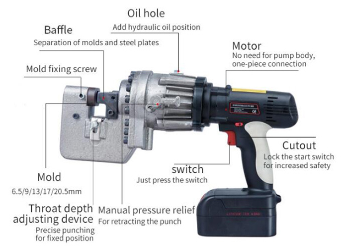
Upper mold replacement method: use a (black) elastic screwdriver to loosen the upper mold (silver white) fixing bolt to the left, slowly remove the upper mold, replace the required upper mold, and then use an elastic screwdriver to tighten the upper mold fixing bolt to the right.
How to replace the lower mold: use a small hexagonal wrench to loosen the screw for adjusting the tightness of the lower mold to the left, then use your fingers or a small tool to push the lower mold out from the bottom of the lower mold, and replace the lower mold that matches the upper mold. Tighten with a small wrench. Note that the typing side of the lower mold should face up and not down. When replacing the mold, first remove the upper mold to replace the lower mold.
Code of Practice
Operators must undergo safety technical training, and only those who are qualified can take up their posts. The moving parts on the machine will exceed the range of the machine base and feet when moving. When the machine is running, no one is allowed to enter the above-mentioned danger zone.
When the machine is going to work, the operator's hand cannot be placed near the die or on the moving platform. The platform discharge height shall not exceed 10 cm. During the operation of the machine, it is not allowed to overhaul and adjust the mold.
