Incremental Encoder Working Principle
The incremental rotary encoder converts the timing and phase relationship of the angle code disc through two photosensitive receiving tubes, and obtains the increase (positive direction) or decrease (negative direction) of the angle code disc angular displacement.
The working principle of incremental rotary encoder is shown in the figure below.
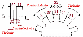
In the figure, the spacing between points A and B is S2, which correspond to two photosensitive receiving tubes respectively, and the grating spacings of the angle encoder are S0 and S1 respectively. When the angle encoder rotates at a constant speed, it can be seen that the ratio of S0:S1:S2 in the output waveform is the same as the ratio of S0:S1:S2 in the actual picture. Similarly, when the angle encoder rotates at a variable speed, the S0 in the output waveform: The S1:S2 ratio is still the same as the S0:S1:S2 ratio of the actual graph.
Through the output waveform diagram, we can know that the sequence of each motion cycle is:
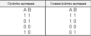
We save the current A and B output values and compare them with the next coming A and B output values to get the rotation direction of the angle encoder.
If the grating S0 is equal to S1, that is, the angle between S0 and S1 in radians is the same, and S2 is equal to 1/2 of S0, then it can be obtained that the movement displacement angle of the angular encoder is 1/2 of the angle of S0 in radians, and then Divide by the time used to get the angular velocity of this angular encoder movement.
When S0 is equal to S1 and S2 is equal to 1/2 of S0, the motion direction position and displacement angle can be obtained in 1/4 of the motion cycle. If S0 is not equal to S1 and S2 is not equal to 1/2 of S0, then 1 the movement direction and displacement angle can be obtained only after the movement period.
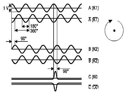
The incremental encoder actually used outputs three groups of square wave pulses A, B and Z (some are called C-phase). The phase difference between the two groups of pulses A and B is 90º, and the rotation direction and rotation speed can be judged. The Z-phase pulse is also called the zero pulse (sometimes also called the index pulse), which outputs a pulse for each revolution. The Z-phase pulse represents the zero reference bit. Through the zero pulse, the zero reference bit of the encoder can be obtained. Used for datum point positioning, as shown in the figure below.
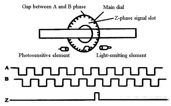
When the shaft of the incremental encoder rotates, there is a corresponding pulse output, and its counting starting point can be set arbitrarily, which can realize multi-turn infinite accumulation and measurement. One rotation of the encoder shaft will output a fixed number of pulses. The number of pulses is determined by the number of lines of the grating on the encoder code disc. The number of pass or dark lines provided by the encoder per 360-degree rotation is called resolution, also known as resolution. It is called resolution division, or how many lines, generally 5 to 10,000 lines per revolution. When the resolution needs to be improved, the A and B signals with a 90-degree phase difference can be used to multiply the frequency or replace the high-resolution encoder.
Incremental encoder accuracy depends on mechanical and electrical factors such as: grating indexing error, disc eccentricity, bearing eccentricity, errors introduced by electronic readout devices, and inaccuracies in the optics, which exist in any encoder.
The signal output of the encoder has various forms such as sine wave (current or voltage), square wave (TTL, HTL). And all can use differential drive mode, including symmetrical A+/A-, B+/B-, Z+/Z- three-phase signals, due to the connection with symmetrical negative signal, the electromagnetic field contributed by the current to the cable is 0, and the signal is stable and attenuated. The smallest, the best anti-interference, can transmit a long distance, for example, for a TTL encoder with a symmetrical negative signal output, the signal transmission distance can reach 150 meters. For HTL encoders with symmetrical negative signal output, the signal transmission distance is up to 300 meters.