What is an Incremental Encoder?
An incremental encoder is a rotary sensor that converts rotational displacement into a series of digital pulse signals. These pulses are used to control angular displacement, and if the encoder is combined with a gear rack or screw, it can also be used to measure linear displacement. The electrical signals generated during rotation can be processed by the following devices: CNC devices (CNC), programmable logic controllers (PLC) control systems, etc. Encoders are mainly used in machine tools, robots, motor feedback systems, and measurement and control devices.
Structure of Incremental Encoder
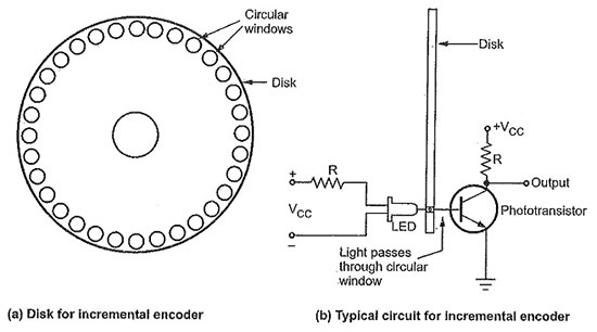
The incremental encoder consists of a code disk, sensitive components, and a counting circuit.
- Code disk: The incremental encoder sets up an inner track and an outer track towards the code disk, with two outer tracks: the first outer track is an incremental counting track, which sets a sector based on the resolution, that is, only one bit track; The second outer orbit is the directional orbit, which has the same number of sectors as the counting orbit, but only moves half of the sectors. If a cycle consists of two sectors (conductive non-conductive), then the outputs of these two orbits differ by 90 ° (electrical angle), either leading or lagging, used to identify whether they rotate clockwise or counterclockwise, and thus determine whether the counter performs subtraction or addition counting. The inner orbit is called a reference orbit, which has only one individually marked sector to provide a reference point. Its output pulse will be used to return the counter to the encoder's binary or cyclic code that can indicate absolute position. The "1" output of each bit is only an increase in angular displacement.
- Sensitive components: The sensitive components of incremental encoders are generally contact brushes or non-contact optoelectronic or magnetoelectric systems, which are compatible with the encoder disk.
- Counters: The incremental encoder calculates the increment of angular displacement, so in order to calculate the actual size and direction of angular displacement relative to a certain reference position, a counter must be set. The counting pulse sent to the counter is output by the Schmidt trigger circuit.
The Working Principle of Incremental Encoder
When the incremental encoder rotates its shaft, there is a corresponding pulse output, and the determination of the rotation direction and the increase or decrease of the number of pulses are achieved through the use of the direction judgment circuit and counter at the rear. Its counting starting point can be arbitrarily set to achieve infinite accumulation and measurement of multiple circles. You can also use the Z signal of one pulse per revolution as a reference mechanical zero position. One revolution of the encoder shaft will output a fixed pulse, and the number of pulses is determined by the number of lines in the encoder grating. When it is necessary to improve resolution, the A and B signals with a 90 degree phase difference can be used to double the original pulse number, or a high-resolution encoder can be replaced.
Reading of Incremental Encoder
The reading system is based on the rotation of a radial indexing disk (code disk) composed of alternating transparent and opaque windows, while being vertically illuminated by an infrared light source, which projects the image of the code disk onto the surface of the receiver. The receiver is covered with a layer of diffraction grating, which has the same window width as the code disk. The job of the receiver is to sense the changes caused by the rotation of the optical disc, and then convert the light changes into corresponding electrical changes. To raise the low-level signal to a higher level and generate square pulses without any interference, electronic circuits must be used for processing. The reading system usually adopts a differential method, which compares two different signals with the same waveform but a phase difference of 180 ° (electrically), in order to improve the quality and stability of the output signal. The reading is formed based on the difference between two signals, thereby eliminating interference. This method is called the "common offset method" because the interference signal overlaps each waveform in the same way.
Advantages of Incremental Encoder
- Small size, precision, high resolution with simple construction
- Easy installation, diverse interface forms, and long mechanical life
- Strong anti-interference ability, reasonable price, and high reliability
- The average lifespan of machinery can exceed tens of thousands of hours
- Suitable for long-distance transmission
In summary, incremental encoders are a common sensor used to measure the position and motion information of mechanical systems. Although they cannot provide absolute position information, they are very useful in many industrial and mechanical applications to ensure accuracy, control, and automation.
