ATO VFD Communicates with HMI Touchscreen by using Modbus
I. Introduction
VFD provides the universal RS485 protocol communication interface in industrial control to the users. The communication protocol adopts MODBUS standard communication protocol. It supports the RUT and ASCII two transmission means. The detailed MODBUS protocol and the definition of the parameters in VFD communication protocol are introduced in the instruction manual of ATO VFD.
II. Requirements of communication case
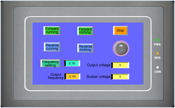
VFD and the display control HMI touchscreen is communicating through MODBUS, so as to realize the stopping, frequency setting and status monitoring and other functions of the VFD through the HMI touchscreen.
III. Communication parameters
In order to realize the normal communication between the VFD and the HMI touchscreen, the communication parameters of the VFD are consistent with those of the touchscreen. Furthermore, correct communication terminal will be chosen. The VFD adopts the Modbus RTU transmission mean and the communication format is 1-8-1 format, which means that the numbers are conveyed in bytes (eight-digit binary system), including one starting position, eight digital positions, one odd/even parity check, one stopping position, CRC (Cyclic Redundancy Check).
Parameter setting of ATO VFD:
| Function code | Name | Setting scope | Minimum unit | Delivery setting | Set value |
| P0.01 | Frequency setting channel selection | 0: Panel analog potentiometer 1: Keyboard UP, DOWN keys setting 2: Digital setting 1, operating panel 3: Digital setting 2, terminal UP/DOWN adjustment 4:Digital setting 3, serial port setting 5: VI analog setting 6: CI analog setting 7: Terminal impulse (PULSE) setting 8:Combination setting (refer to P3.00 parameter) |
1 | 0 | 4 |
| P0.03 | Operating command channel selection | 0: Operating frequency channel of the panel 1: Command channel of the terminal operation 2: Operating command channel of the serial port |
1 | 0 | 2 |
| P3.09 | Communication configuration | LED unit digit, Baud rate selection 0: 1200BPS 1: 2400BPS 2: 4800BPS 3: 9600BPS 4: 19200BPS 5: 38400BPS LED decade, digital format 0: 1-7-2Format, no verification 1: 1-7-1Format, odd verification 2: 1-7-1Format, even verification 3: 1-8-2Format, no verification 4: 1-8-1Format, odd verification 5: 1-8-1Format, even verification 6: 1-8-1Format, no verification LED hundreds, communication mean 0: MODBUS,ASCII mode 1: MODBUS,RTU mode |
1 | 063 | 163 |
| P3.10 | Address of the local machine | 0~248 0: Broadcasting address 248: Act as the host address by VFD |
1 | 1 | 1 |
Note: Other functions of the VFD can be set referring to the instruction manual of ATO VFD.
IV. Communication between the VFD and HMI touchscreen
The general procedure of establishing communication between the VFD and the display control HMI touchscreen will be introduced in the following paragraph in details.
VFD and HMI touchscreen adopt RS 485 communication. The programming software of the touchscreen uses the exclusive SKWorkshop configuration compiling software for the display control SK.
Wiring mode. The back of the touchscreen is connected with 24VDC power supply terminal and nine-needle communication terminal with D-shape public seats. The following is the pin definition of the serial communication.
| Pin number | Definition |
| 1 | TD+ |
| 2 | RXD |
| 3 | TXD |
| 4 | NC |
| 5 | GND |
| 6 | TD- |
| 7 | RTS |
| 8 | RD- |
| 9 | RD+ |
VFD and HMI touchscreen adopt RS 485 communication mode. Its cable connecting diagram is as the following diagram.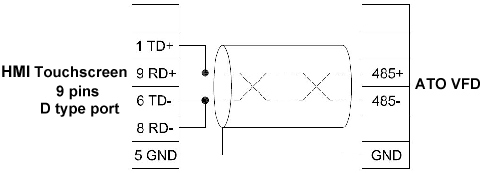
V. Establishment of the HMI touchscreen engineering case
1. Enter into SKWorkshop interface, open file and establish a new project, put in the project name requires to be established in "Project Name".
- Modbus RTU Master: Touchscreen is the modbus master station, device as the slave station (conventional modbus)
- Modbus RTU Slave: Touchscreen is the modbus slave station, device as the master station
- Modbus ASCII Master: Touchscreen is the modbus master station, device as the slave station (ASCII communication)
- Modbus ASCII Slave: Touchscreen is the modbus slave station, device as the master station (ASCII communication)
- Modbus RTU Special: Touchscreen is the modbus master station, device as the slave station (the function code of writing data is 0x10, regardless of the length of the writing data)
- Modbus ASCII Special: Touchscreen is the modbus master station, device as the slave station (the function code of writing data is 0x10, regardless of the length of the writing data, ASCII communication)
- Modbus Master TCP/IP: Touchscreen is the modbus master station, device as the slave station (TCP/IP communication)
- Modbus Slave TCP/IP: Touchscreen is the modbus slave station, device as the master station (TCP/IP communication)
PLC continuous address interval: The readable continuous address number for one time (it has to pay attention in communicating in SCM device or VFD device. If the register address of the device is not continuous or not the integral multiples of 32, for example, when the address of the developed SCM only has 20, it can be changed into 1 at this time).
2. The connecting parameter setting
Here, the Baud rate is consistent with the VFD. HMI touchscreen as the master station: 0. VFD address as the slave station,PLC station number: 1.
Address mode: The standard mode is one master and one slave. The expansion mode is one master and several slaves.
3. How to establish the starting and stopping button?
Take forward starting as an example.
In the parameter setting of the communication protocol of the VFD, the command address to the VFD is 2000H.
2000H inversion decimal positive integer is 8192.
The forward operating command is 0002H. Set the constant address 2.
1 is the defined address of the VFD. 4 is the name of the Modbus register.
Similarly, the reversal starting, stopping and reset functions corresponding to the character button functions can be established. Please refer to the instruction manual of the VFD for the detailed function parameters.
4. How to monitor the parameters of the displaying VFD?
Take displaying the output frequency by the VFD value as an example.
Click the digital output, the address of the VFD output frequency is 2103H, then the screen monitoring address is set to be 1:4*8451, four-digit, 2 decimal places.
The scope in senior selection displays the selected corresponding scope.
Add literal statement and click A statistic text, put in the characters to be compiled.
VI. Project download
Connect USB cable between the computer and the HMI touchscreen. Save, compile and click download.
VII. Off-line simulation