HMI and PLC Programs for VFD Control
Generally, using PLC as an intermediate tool for HMI to control VFD is a good choice. Now, let’s us establish and HMI to control the VFD project. We need to communicate with an Omron PLC and use the PLC commands to control the VFD. Set the PLC model and communication parameters (RS232, Host Link communication protocol) that need to be communicated.
Step 1: Click the right mouse button to create a new RUN button (Button/ Momentary).
- RUN — WB001
- STOP — WB002
- Rated Hz — WB000
- Input Hz — D100
- ENTER — WB008
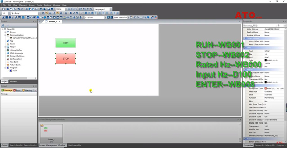
Select the PLC auxiliary relay WB001 (corresponding to Omron PLC W0.01) in the Link2 state. Adjust the button style and edit the button text.
Establish the STOP button in the same way. PLC auxiliary relay WB002 (PLC W0.02).
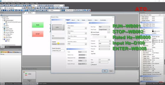
Step 2: New VFD frequency input box (Input/ Numeric Entry).
- Select PLC memory DM area, corresponding to address 100 (PLC D100).
- Set the maximum allowable input value of 60. Select the input style.
- Select the input font size.
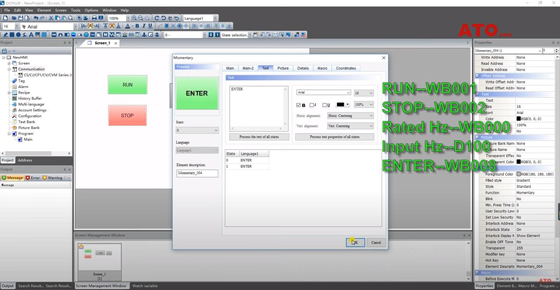
Step 3: Set the ENTER key (Button/ Momentary).
- Corresponding PLC auxiliary relay address is WB008 (PLC W0.08).
- Set the button style and text.
- Set the rated frequency input button (WB000) in a similar manner.
Step 4: Right-click on the “Screen Management Window” to create a new Screen.
- Create a new button on the screen (Button/ Goto Screen)
- Choose to go to the next page.

Step 5: Create a new button to return to the previous page in “Screen2” (Button/ Goto Screen/ Function/ Previous Page).
Step 6: New System Button (Button/ System Menu).
PLC program explanation
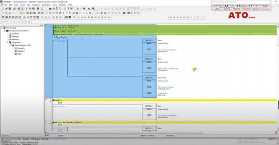
- RS232C Port is the connection port with HMI.
- The communication parameters here should be consistent with the previous HMI communication parameters.
- Serial Option Port is the communication interface with VFD, and the communication parameters are consistent with the internal communication settings of VFD.
- The first paragraph of instructions clears the data in the PLC storage area to be used to prevent the interference of old data (D100, D200, D1300 ~ D1304).
- In the second section, the rated frequency input area (Rated Hz button, WB0000), move the rated frequency into D100.
- The third paragraph, VFD frequency write command.
- W0.00 corresponds to “Rated Hz” of HMI, W0.08 corresponds to “ENTER”.
- The start and stop commands are written to D200, #0001 is the VFD start command, and #0007 is the stop command.
- W0.01 corresponds to the HMI RUN button, W0.02 corresponds to the HMI STOP button.
- VFD RUN and STOP command block.
- W0.03 is the command start auxiliary relay.
- The last section of instruction is the communication set and reset delay program with VFD.
- W0.03 is used as an auxiliary relay for starting and stopping.
- The “RUN, STOP, ENTER, Rated Hz” on the HMI and the external button I0.03 will trigger this block.
- Every time A641.0 is set and reset, VFD and PLC will carry out a data communication.
For more details about HMI and PLC programs for controlling VFD, please view the video below.
