How to Program HMI and PLC?
Thu, May 26 by ATO.com
ATO HMI touch screen can be connected to industrial control equipment such as programmable logic controller, inverter, DC speed regulator and instrument. Its display shows that the digital device that realizes the interaction of human and machine information through input unit to write working parameters or input operation commands. Now let’s program and test the HMI and PLC.
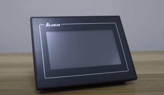
This is a Delta HMI (Human Machine Interface).
Wiring
- Connect the 24VDC power supply.
- The Omron PLC CO1E N40DT-D also requires 24VDC power supply.
- Connect the dedicated communication line (RS232 interface).
- Connect with PC.
Program
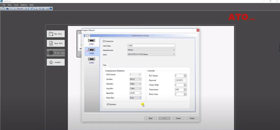
- Open the HMI software, create a new project, and select the corresponding HMI model.
- Set up the PLC that needs communication (OMRON PLC CP1E N40DT-D).
- Set the communication parameters required for communication with PLC. (link2, RS232, 8, 1, 38400, Even).
- Click the right mouse button to create a new button/ Set Value.
- Double-click the drawn button, and then Main/ write address/ link2/ D/ 100. (Corresponding to the internal storage area of the PLC D100).
- Text, enter Set Value.
- Picture the button style.
- Click the right mouse button to create a new button/ Maintained/ WB/ 000 (corresponding to PLC internal virtual relay W0.00).
- Text/ Set W0.00.
- Choose the button style.
- Compile the project to see if an error is reported.
- Download the project to the HMI.
- After the download is complete, the HMI display screen is the same as the screen in the project software.
Omron PLC software operation
- Create a new PLC program project
- Select the corresponding PLC series.
- Set the communication parameter information corresponding to HMI.
- 38400, 8, 1, e, the default host link mode.
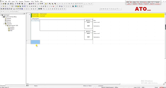
- Clear the storage area of D100 and D200 (MOV #0000 D100 & MOV #0000 D200).
- Establish W0.00 virtual intermediate relay and wait for the state of MOV instruction. (MOV #1234 D200).
- Monitor D100 and D200 storage area data.
Compile the program.
Test
- Connect the PLC and download the program to the PLC. (Note that setting is checked.)
- Restart the PLC. At this time, the PLC and HMI have been communicated. And the PLC communication light is always on.
- View D100 and D200, the data is 0.
- Click the button Set Value on the HMI to set parameter 543. At this time, the data in the D100 storage area is 021F Hex.
- View the decimal value as 543.
- Pay attention to observe W0.00 on PLC.
- When you press Set W0.00 on the HMI, W0.00 on the PLC is turned on.
- #1234 was transferred to the D200 storage area.
- View D200, the value is 1234 Hex.
- Reset the button on the HMI, W0.00 is reset.
The communication example between HMI and PLC is completed.
View the video below to learn more details about HMI and PLC programming and testing.
