How to Setup a Digital Panel Meter?
The digital panel meter displays the voltage, current value or other standard signal transmission display value in the electrical circuit by digital direct reading; the product has the advantages of good stability, strong anti-interference, high cost performance, and the product is small in size and can be directly replaced original pointer meter. It is widely used in voltage stabilizers, spot welding machines, calibration benches and various electrical equipment and control systems that have certain restrictions on the size of the instrument. Now we will introduce how to use a digital panel meter.
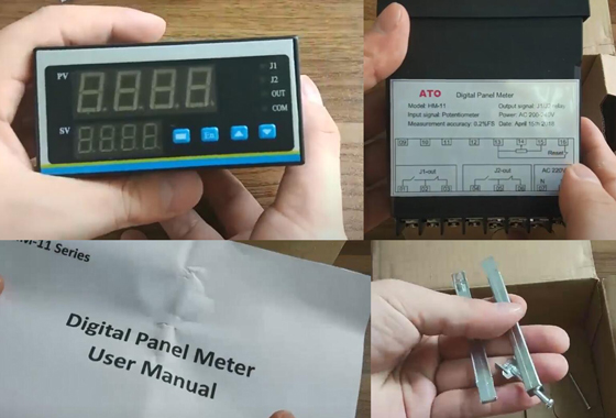
This is ATO digital panel meter.
Package includes a digital panel meter, an instruction manual, a set of mounting bracket.
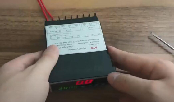
Connect the power line.
This is an AC 220V single-phase power supply.
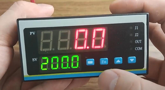
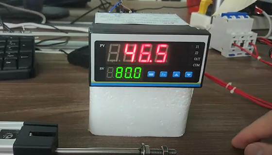
Now is the performance of power on. Above red is the current measured value (PV). Below green is the set value (SV). “En” is a function key. We can try to press it.
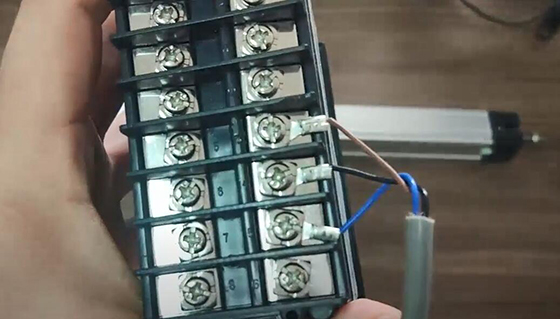
Connect the displacement sensor.
Start to demonstrate displacement sensor. Terminal 13, 14 and 15 are used to connect displacement sensor.
Panel operation demonstration.
In different position, sensor will feed back different potentiometer signal to the digital panel meter. Demonstrate the zero/ resent operation. The button in the left of panel is a zero button. We can reset sensor when it move to any position.
Function settings.
Demonstration of J1 alarm function and other functions. Press “En” to set alarm parameters. When “LOC” is changed to ON, the setting value of alarm points can be modified. Confirm the current setting by “En” key. In the Cd function settings, change 800 to 808, and enter the parameter setting state. Confirm by “En”.
- “dot” is setting of decimal places.
- 1nPL represents the lower limit of range setting value.
- 1nPH represents the upper limit of the range setting value.
- J1-H is the J1 alarm function setting.
- Underneath off is on behalf of closing J1 alarm function.
- HH indicates the ultra high alarm of the measured value.
- LL indicates the ultra low alarm of the measured value.
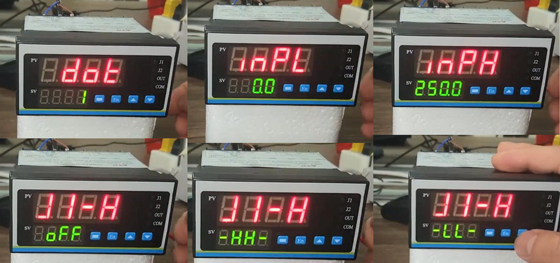
Now we set J1 to HH. Set up J2 ~ J4 in the same way.
- bS is a transmission mode.
There are optional output signals, such as 4-20mA, 0-10mA, 0-20mA, 1-5V and 0-5V.
- bS-L and bS-H are the setting of the upper and lower limit of transmit output.
Behind these are the correction settings.
- Addr is the communication address instrument code.
- bAUd is the communication baud rate.
- LdiS is the setting for the bottom row display value.
Alarm parameter settings.
Demonstration of setting the upper and lower limit of J1 alarm. Press “En” function key to set LoC to ON.
- J1HA is the upper limit setting.
- J1HF is a lower limit setting.
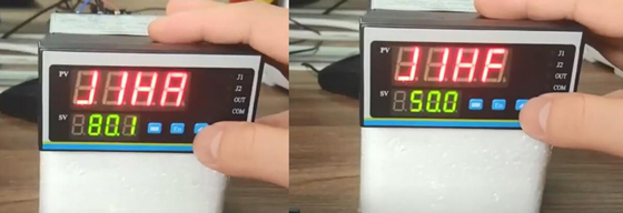
Press “En” to end the setting. If the current value exceeds 92 of the set value, J1 starts the alarm. When the displacement value is lower than J1HF, the J1 alarm will disappear.
You can view the video below if you want to know more about how to use an ATO digital panel meter.
