How to Use a Load Cell?
Load Cell Handling
Handle gently, particularly small capacity sensors of elastomers made from alloy aluminum. Any impact or drop will cause great damage to the metering performance. For high-capacity load cells, it's generally more heavier, so proper lifting appliance (such as chain block, electric block) shall be adopted when moving or installing. The base for installing the load cell shall be plane and clean without any oil film or adhesive film. The base should have enough strength and rigidity, which is generally higher than that of the load cell.
Load Cell Installation
The load cell has a certain overload capacity, but it shall still be prevented from overloading in installation. It should be noted that even a short-term overload can still cause permanent damage to the sensor.
During the installation, a pad with the same height of the sensor could be first used instead if necessary, then replace the pad with the sensor. If the sensor is fixed with screws, the screw should have a certain fastening torque and screwing thread depth. Generally, high strength screws should be used.
Avoid Contamination
The load cell shall be set with several "baffles" around or even covered with thin steel plate, thus preventing the debris from contaminating the sensor and some movable parts, because such a "contamination" often restrains the movable parts and thereby affects the precision of the load cell. Whether a system has movement restriction can be judged with the following method. Namely adding or reducing about 1/1000 of rated load on the load platform, and then observing whether the load display gives a reflect. If it does, that means the movable parts are not contaminated.
Be Careful with Electricity
Sensor wiring & signal integrity
All cables leading to the display circuit or leading from the circuit should be shielded cables. Connections and ground points of the shield cables shall be properly set. In case the cables are not grounded through mechanical frames, they shall be grounded externally; however, shield cables are not grounded after connection, but suspended. Notice:
- 3 sensors are full-parallel connected.
- The sensor is a 4-wire system, but it shall be changed into a 6-wire system in the load cell junction box.
- Read-out circuit of the sensor's output signal should not be placed in the same box with devices that can produce strong interference (such as silicon control, contactor) or that produce considerable heat. If it's unable to be guaranteed, a baffle plate shall be set between them while a fan shall be installed in the box.
- The electronic circuit used to measure the output signal of the sensor shall be equipped with independent supply transformer, but not use the same power supply with contactor and other devices.
Physical protection & environmental requirements
The sensor should use twisted copper wires (sectional area of 50mm2) to form electric bypass, so as to protect them from damages caused by welding current or lightning strike. The sensor should avoid intense thermal radiation in use, particularly the unilateral intense thermal radiation.
Cable separation & shielding interference
Signal cables of electrical connection equipment (such as the sensor) shall not be arranged in parallel to the power line or control line of strong electricity. For example, the sensor's signal cables shall not be placed in a same pipeline with the power line or control line of strong electricity. If they have to be arranged in parallel, the distance between cables shall be more than 50CM while the signal cables are wrapped by a metal tube.
Quality assurance & final inspection
In any case, the power line and control line should be twisted together, corresponding degree of coincidence shall be 50 turns per meter. If the sensor's signal line needs to be extended, a special sealed cable box shall be used. If such a box is not adopted and the cables are connected directly (soldering end), special attention should be paid to sealing and moisture-proofing.
After well connected, check the insulation resistance, which should meet the standard (2000~5000M). If necessary, the sensor should be recalibrated. If the signal cable is extremely long while a high measurement accuracy is required, a cable compensation circuit with relay amplifier shall be adopted.
Eliminate Lateral Force Interference
It's better to use structural parts with automatic positioning (reset) function, such as the spherical bearing, joint bearing, positioning fastener. They can prevent partial lateral forces acting on sensors.
What is to be explained is that some lateral forces are not caused by mechanical installation, such as the lateral force caused by thermal expansion, lateral force caused by wind power, as well as the lateral forces caused by vibrations of the agitator on some container-like load apparatus. Some parts of the load apparatus have to be connected to the scale (such as the feeding pipeline of container scale), we should make them as soft as possible in the main shaft direction of sensor loading, so as to avoid them "eating" actual loads of the sensor and causing errors.
Horizontal Adjustment
On one hand, installation surface of installation base for single sensor should be adjusted horizontally.
On the other hand, installation surfaces of installation bases for multiple sensors should be adjusted to a horizontal plane as far as possible (with a level gauge). Particularly, if a load system has more than three sensors, the installation surfaces shall be adjusted to a horizontal plane, so as to ensure all sensors to bear equal load. Loading direction of each load cell is determined; we shall have to add load on this direction when using. Lateral force, additional bending moment and torsional force should be avoided as far as possible.
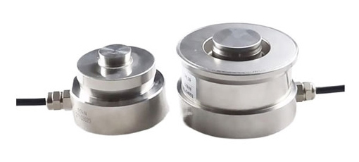
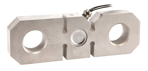
There are various load cells available for you to choose from at ATO.com, strain gauge load cell, micro load cell, tension and compression load cell and so on.
