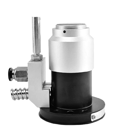
How to Use the Tool Setter?
The working principle of the tool setter is as follows:
- After the linear motion axes of the machine tool return to their respective mechanical reference points, the relative position relationship between the machine tool coordinate system and the fixed coordinate of the tool setter is established.
- No matter using automatic programming control or manual control mode to operate the tool setting instrument, when moving the tool along a selected axis, making the tool tip (or the outer diameter of the power rotary tool) close to and touch the corresponding plane of the four probes on the tool setting instrument, and triggering the high-precision switch sensor through the swing of the flexible support rod, the switch will immediately inform the system to lock the movement of the feed axis. Because the numerical control system takes this signal as an advanced signal to process, so the action control will be extremely fast and accurate.
- Because the linear feed axis of CNC machine tool is equipped with pulse encoder for position loop feedback, the CNC system also has a counter to memorize the actual position of the feed axis. At this time, the system only needs to read out the accurate stop position of the axis, and through the automatic conversion of the relative relationship between the machine tool and the tool setter, the initial tool offset value of the tool tip (or diameter) of the axis tool can be determined. In other words, if it is measured in the machine tool coordinate system, it is equivalent to determining the distance between the reference point of the machine tool and the zero point of the machine tool coordinate system, the distance between the tool measuring point and the zero point of the machine tool coordinate system, and the actual deviation between them.
- Whether it is the tool wear after cutting or the tool tip change after the hot elongation of the screw, the CNC system will automatically compare and calculate the new tool offset value with the initial tool offset value, and automatically fill the error value to be compensated into the tool offset storage area. Of course, if a new tool is replaced and the tool is adjusted again, the offset value obtained should be the new initial tool offset value of the tool.
Tool setting accuracy
According to the relevant data and practice, the repeatability of the tool setting probe is 1 um, and that of the chuck less than 15 inches is 5 um. The repeated accuracy of the tool arm can reach 8um for the chuck of 18 inches and above. This precision can meet the needs of most users without trial cutting. The use of tool setter reduces the auxiliary time of the machine tool and reduces the rework and scrap rate. The efficiency and accuracy of the machine tool can be significantly improved when the machine tool is used from the beginning to the end.
Operation procedure of tool setter
- Daily maintenance of tool setting instrument
- Check whether the lubrication system is normal every day;
② The spindle must be clean and coated with anti-rust oil;
③ The test rod must be wiped clean and coated with anti-rust oil;
④ After use, please keep or add clean antirust oil, and timely remove debris, dust, scrap iron, etc;
⑤ Clean the tool setter cover every day;
⑥ Please be sure to use clean antirust oil, remember not to use gasoline, acetone solvents;
⑦ Please wrap with protective cover when not in use. - Operation precautions of tool setter
① When operating z-axis fast displacement, please do not pull vigorously, press the handle inward, and then use the fine-tuning hand wheel when moving close to the tool;
② When measuring the tool, please contact the side head with the back of the tool to avoid damaging the measuring head and gauge;
③ Before each tool setting, the data must be corrected with a test rod, and the out is 0.02mm;
④ Loosen the x-axis fixing screw before operation;
⑤ Loosen the z-axis fixed counterweight screw before operation;
⑥ Please turn off the power after use. - Operating instructions
- X axis is returned to "0":
① Please wipe and clean the spindle and test rod at the same time;
② Move the Z-axis (lift) dial indicator holder 90 degrees clockwise to avoid hitting the test rod when the X-axis returns to zero;
③ Adjust the X-axis gauge probe to touch the test rod, so that the gauge pointer touches the first 0 position in the clockwise direction;
④ Set the X-axis display data to the number of the radius of the test rod, and it will return to "0". - Determine the "0" action of the test rod
① Install the tool into the spindle and lock the nut to fix it.
② Rotate the spindle so that the tool tip contacts the x-axis probe and turn the pointer of the gauge to the first "0" position;
