
How to Wire and Configure a VFD for 3-Wire Control?
Three-wire control is a common method of operating a motor through a variable frequency drive (VFD). It uses external push buttons connected to the drive's digital inputs to control motor operation without directly switching the motor's power supply. This article explains how to configure the VFD for 3-Wire Control Mode 1, using three push buttons to control forward and reverse rotation and the enable function for local machine operation.
- What Components Are Needed
- How to Wire the VFD
- How to Configure the VFD Parameters
- How to Test the 3-Wire Control System
- Conclusion
I. What Components Are Needed
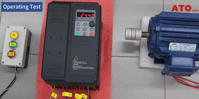
The setup uses two main devices as a basic VFD motor control system, with an additional three-push-button assembly.
Unlike a power-switching arrangement, the push buttons send control signals to the VFD's digital inputs. The drive processes these signals and controls the motor accordingly.
II. How to Wire the VFD
1. Power and Motor Wiring
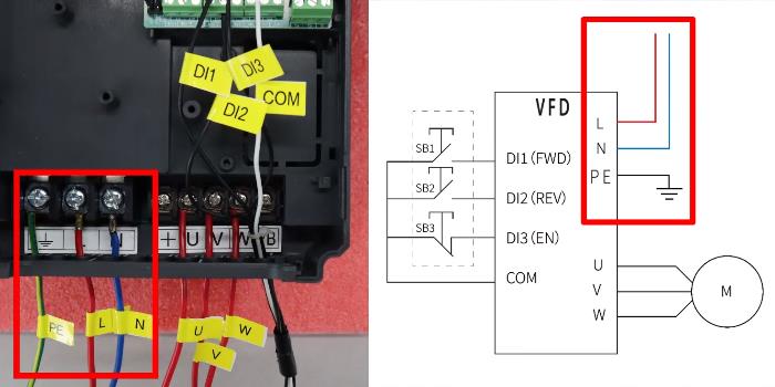
Connect the live and neutral wires to the VFD's L and N terminals, respectively, and connect the protective earth wire to PE. Then connect the three-phase motor to the VFD's U, V, and W output terminals.
2. Push-Button Wiring
Connect the three external push buttons to the VFD's digital input terminals as follows:
| Push Button | VFD Terminal | Function |
| SB1 | DI1 | Forward running |
| SB2 | DI2 | Reverse running |
| SB3 | DI3 | Enable function |
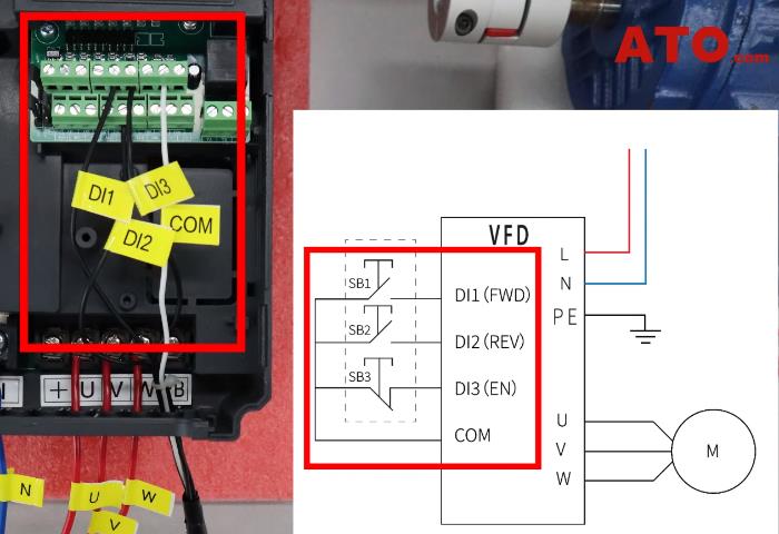
All three digital inputs share the COM reference. SB3 must use a normally closed (NC) contact so that the enable condition remains active while the contact is closed. Always consult the user manual to verify the appropriate resistor ratings and terminal identification before installation.
III. How to Configure the VFD Parameters
After completing the wiring, configure the GK3000-CT VFD to recognize the three external control inputs.
1. Access the Parameter Menu
Use the VFD keypad to enter and adjust the parameters:
- Press PRG to open the parameter settings.
- Use UP and DOWN to navigate through the parameters or change their values.
- Press RIGHT to move between digits when editing a value.
- Press ENTER to confirm the setting.
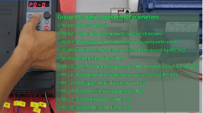
2. Configure the P0 Parameter Group
Configure the required basic operating parameters in the P0 group. These settings depend on the intended application and drive configuration, so refer to the user manual for the appropriate values.
3. Configure the P4 Parameter Group
Set the following parameters to enable three-wire control mode 1 and assign the three digital inputs.
| Parameter | Setting | Function |
| P4-11 | 2 | Activate 3-wire control mode 1 |
| P4-00 | 1 | Assign DI1 to forward running |
| P4-01 | 2 | Assign DI2 to reverse running |
| P4-02 | 3 | Assign DI3 to the enable terminal |
Verify each parameter after saving it. The input assignments must match the physical wiring for the push buttons to perform their intended functions.
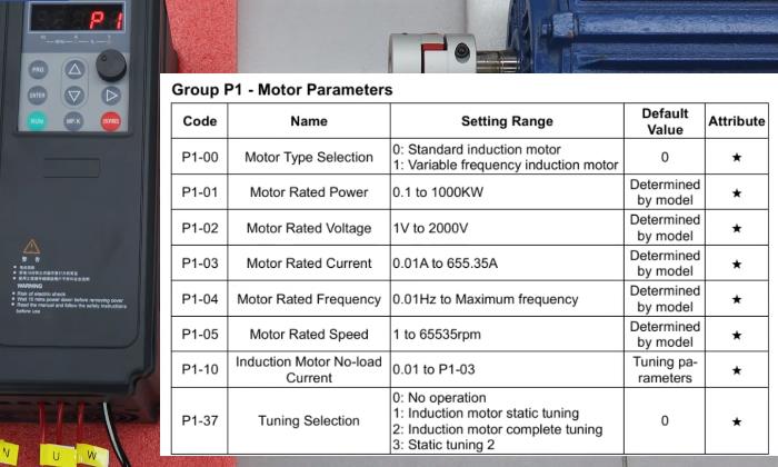
4. Enter the Motor Parameters
Navigate to the P1 parameter group and enter the induction motor information according to the motor nameplate.
Once the wiring and parameter settings have been checked, the system is ready for an operating test.
IV. How to Test the 3-Wire Control System
After checking the wiring and parameters, test the push buttons one at a time.
- Check the enable condition. Confirm that SB3's NC contact is closed.
- Start forward running. Press SB1 and verify that the motor rotates forward.
- Adjust motor speed. Turn the VFD panel knob to change the output frequency and motor spee
- Disable the drive output. Press SB3 to open the enable circuit and verify that the VFD stops its output.
- Start reverse running. Restore the enable condition, then press SB2 to command reverse operation.
- Test stopping again. Press SB3 and verify that the motor stops according to the configured behavior.
V. Conclusion
Configuring the VFD for three-wire control mode 1 allows external push buttons to manage forward and reverse running, while the VFD panel can still be used to adjust motor speed. For a visual demonstration of the complete setup, watch the video below to see the configuration in detail.
Looking for VFDs and other industrial automation components for your next project? Visit ATO.com to explore the available product range and find components suited to your application.
