
How to Fix Servo Runaway by Adjusting the Electronic Gear Ratio?
An incorrect electronic gear ratio can cause unexpected servo motor movement in a PLC-based positioning system. The electronic gear ratio determines the relationship between incoming command pulses and the commanded motor movement. If the ratio is configured incorrectly, the motor may travel much farther than expected or exhibit abnormal motion. This guide explains how to configure the electronic gear ratio, wire the control system, program the PLC, and test the servo motor response under different parameter settings.
- Required Components
- System Architecture
- Physical Setup and Wiring
- Wiring Diagram and Connections
- Servo Drive Configuration
- PLC Programming
- Operation Test
- Conclusion
I. Required Components
- PLC
- Servo Drive
- Servo Motor
- Three-Button Pendant Station (CW, CCW, STOP)
- S-ON Enable Button
- E-Stop Button
- Three Interposing Relays
II. System Architecture

The system uses pulse-driven positioning. The PLC generates pulse commands and sends them to the servo drive, which interprets the signals and controls the motor's rotational movement.
III. Physical Setup and Wiring
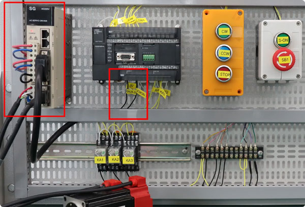
The three control buttons connect to the designated PLC inputs. The E-stop SB1 connects to a PLC input and is wired in series with the S-ON enable button inside the junction box. The S-ON signal connects to terminal 7 of the CN3 connector, while the PLC pulse outputs connect to the servo drive to control motor movement.
IV. Wiring Diagram and Connections
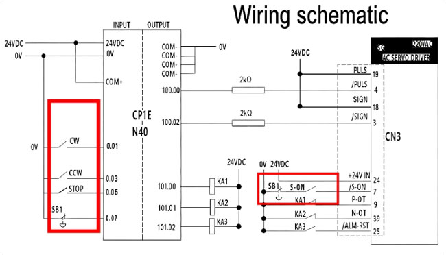
The wiring diagram highlights the control button wiring, the S-ON and E-stop circuit, and the PLC input and output connections. The CN3 wiring table identifies each signal by wire color and terminal number. Connect each wire to the correct pin or screw terminal according to the wiring specifications.
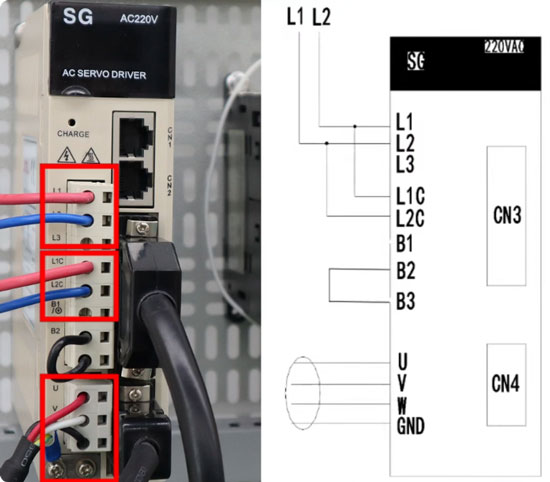
The diagram also shows the servo drive connections: L1 and L2 for the main power supply, L1C and L2C for control power, and U, V, W, and GND for the motor connection. The motor encoder connects through its dedicated feedback interface.
The limit and alarm relays complete the motion protection circuit, supporting overtravel protection and servo alarm reset functions.
V. Servo Drive Configuration
Configure the servo drive for position control and set the electronic gear ratio as follows.
Step 1: Select Position Control Mode
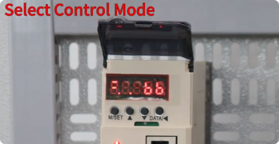
Press M/SET to access parameter Pn000, then press DATA to edit it. Set the value to n.0010 and press M/SET to confirm.
Step 2: Set the Electronic Gear Ratio Numerator
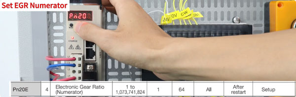
Locate parameter Pn20E, the electronic gear ratio numerator. Set Pn20E = 1 for the initial test, then press M/SET to confirm.
VI. PLC Programming
Create a new PLC project, select CP1E as the device type, and choose N40 as the CPU type. Configure the ladder logic with the following control functions:
- SB1: Uses a normally closed contact and interrupts both direction commands.
- CW: Generates forward pulse output at 100 Hz.
- CCW: Generates reverse pulse output at 100 kHz.
- STOP: Stops the pulse output.
- KA1: Prevents movement beyond the clockwise limit.
- KA2: Prevents movement beyond the counterclockwise limit.
- KA3: Resets servo alarm codes that support external reset operation, according to the drive documentation.
VII. Operation Test
Normal Operation
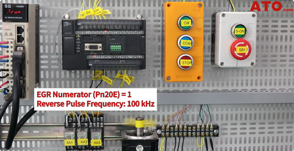
Set Pn20E to 1, enable the servo, and run the CCW test. At pulse frequencies up to 100 kHz, the motor runs smoothly without abnormal acceleration or overshoot, demonstrating a predictable response to the PLC commands.
Incorrect Electronic Gear Ratio
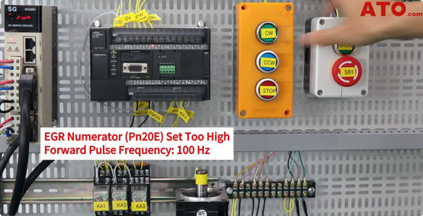
For comparison, set Pn20E to an extremely large value while keeping Pn210 very small. This creates an excessively high electronic gear ratio, causing the motor to move far beyond the expected position despite a low pulse frequency.
The electronic gear ratio determines how command pulses translate into commanded motor movement. An incorrect ratio can result in excessive displacement and severe overshoot, potentially causing a servo runaway condition.
To avoid this problem, calculate the ratio according to the mechanical requirements and the servo drive manufacturer's instructions. Refer to the drive manual for calculation examples, verify the parameter settings, and confirm the motor response under controlled conditions before normal operation.
VIII. Conclusion
The electronic gear ratio plays a key role in PLC servo positioning. An incorrect setting can cause excessive motor movement and overshoot, potentially leading to servo runaway.
Calculate the ratio according to the servo drive manual and verify the motor response through controlled testing to help ensure accurate, predictable positioning. For more industrial automation information, visit ATO.com.
