Safe Use of Clamp Meter
Clamp meter is the abbreviation of clamp ammeter. It is a portable measuring instrument that can directly measure the AC current of the circuit without disconnecting the circuit. It is called a clamp ammeter because of its shape with a movable opening in the shape of a clamp. Common clamp meters do not have the ability to measure AC and DC voltages of 1kV or above. It is recommended not to measure parameters higher than this voltage to avoid personal electric shock.
First of all, the requirement for the use of the clamp meter is that the two power cords can be separated, and the strands cannot be tested; at the same time, we can see that there are generally three jacks on the clamp multimeter: 1. VQ is the jack for measuring voltage resistance, generally insert the red test lead; 2. COM is the common test hole of each gear, generally insert the black test lead; 3. Some clamp meters also have a hole with a lightning symbol, which is the hole for detecting the line of fire, that is, insert the red test pen into the hole. The black test pen will not be connected to the multimeter. Turn the dial to indicate the lightning symbol position, and use red The test leads can measure charged objects.
The figure below is an illustration of how to use the clamp meter, and we will interpret it in detail below.
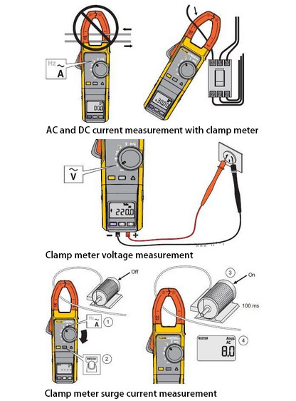
Illustration of how to use clamp meter
- Correctly select the gear of the clamp meter, as shown in the figure, select the AC current gear.

- Open the clamp meter jaws and connect the clamp meter to the circuit under test. The connection method shown in the figure below is a wrong example, so that the current consumption of the circuit cannot be measured, but the leakage current of the circuit, which is zero under normal circumstances.

- The connection method shown in the figure below is a correct example. Only a single power cord of the circuit under test can be passed through the jaws. Two wires can be tested separately, the two measured values should theoretically be equal, otherwise the circuit is abnormal and the leakage current is large. The measured current value of the test circuit shown in the figure is 4.5A.

- If you need to test the starting current of the household appliance, you should press the "INRUSH" button on the basis of the previous step and then start the household appliance. The pressing process is shown in the figure.

- After pressing the "INRUSH" key, when the household appliance still does not start, the meter displays as shown in the figure.

- After starting the household appliance, the measured starting current is shown in the figure below.

Analysis of key points in the use of clamp multimeter
When in use, turn the range switch to the appropriate current position, hold the meter body, and press the switch with your thumb to open the jaws and introduce the measured wire into the center of the iron core. Then, when the switch is released, the iron core is automatically closed, and the current of the wire under test produces alternating magnetic lines of force in the iron core. The current value is reflected on the meter and can be read directly.
- Read the instruction manual carefully before using the digital multimeter to familiarize yourself with the function of the power switch and limit switch, input jacks, sockets, and various function keys, knobs, and accessories. In addition, you should also understand the limit parameters of the multimeter, the characteristics of overload display, polarity display, low voltage display, and other indicator displays and alarms, and grasp the law of change in the position of the decimal point.
- Before each measurement, check again whether the measurement item and the limit switch are in the correct position, and whether the input jack (or dedicated jack) is selected correctly.
- The meter will show the phenomenon of hop count when measuring, wait until the displayed value is stable before reading.
- Although the digital multimeter has a relatively complete protection circuit inside, it is still necessary to avoid operating errors as much as possible.
- If only the highest digit displays the number "1" and the other digits are blanked, it proves that the meter has been overloaded and a higher limit should be selected.
- It is forbidden to flip the limit switch when measuring voltages above 10OVI or currents above 0.5A to generate arcs and burn the contacts of the transfer switch.
- The number with the danger mark next to the input jack represents the limit value of the input voltage or current of the jack.
- Aluminum-shaped multimeters must not measure the current of high-voltage lines, and the voltage of the tested line must not exceed the voltage level specified by the clamp meter (generally no more than 500 volts) to prevent insulation breakdown and personal electric shock.
- The measurement should estimate the value of the measured current, select the appropriate range, and cannot use the small range gear to measure the large current.
- Before measuring, please pay attention to the range switch to the corresponding AC current gear. Voltage gear and resistance gear cannot be used to measure current. Never use resistance gear and current gear to measure voltage, otherwise the meter will be burnt.
Only one wire can be clamped in each measurement. When measuring, the wire under test should be placed in the center of the jaws to improve the accuracy of the measurement. The best thing is to flatten the watch body with your hands, as far as possible to prevent the wire from leaning against the jaws and the watch body. After the measurement, the range switch must be turned to the maximum voltage range position, and then the power switch is turned off to ensure safe use next time.
