How to Use a Clamp Meter?
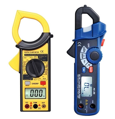
The digital clamp meter is a meter used to measure the current of the running electrical circuit. With this instrument, the current can be measured under uninterrupted power conditions. It can be used to measure AC and DC voltage, AC current, resistance, capacitance, diode forward voltage drop, circuit continuity, frequency and duty cycle. The greatest convenience of measuring AC current is that only one wire to be measured is placed in the intersection. Moreover, the measured AC current frequency range can be as wide as 1 kHz. The display of ATO clamp meter is equipped with background light, which is convenient for working under the condition of low light.
The common operations of the digital clamp meter are as follows:
AC current measurement
- Rotate the switch to ACA 1000A gear.
- Keep the switch on the loose status.
- Press the trigger and open the jaws to clamp one wire. If more than two wires are clamped, the measurement is invalid.
- Read the value. If the reading is lower than 200A, it is required to turn the switch to ACA 200A to improve accuracy. If limited by environmental conditions, such as in the dark, it cannot be read directly. At this time, you should press the hold button and take it to a bright place to read.
AC and DC voltage measurement
- When measuring DC voltage, the switch needs to be turned to ACA 200A gear; when measuring AC voltage, it is necessary to turn the switch to ACV 750V gear.
- Maintain the switch at a loose status.
- Connect the red ammeter to the “V/Q” end and connect the black ammeter to the “COM” end.
- Connect the red and black meters to the tested wire in parallel.
Resistance measurement
- Rotate the switch to the resistance gear with the appropriate range.
- Maintain the switch at a loose status.
- Connect the red ammeter to the “V/Q” end and connect the black ammeter to the “COM” end.
- Connect the red and black meters to the two ends of the measured resistance respectively. When measuring the online resistance, the line should be disconnected from the source and the capacitor connected to the resistance should be discharged.
On-off test
- Rotate the switch to 200n gear.
- Connect the red and black meters to the “V/Q” end and “COM” end.
- If the resistance between the red and black meters is less than (50±25) Q, the built-in buzzer will sound.
High resistance measurement
- Turn the switch to “EXTERNAL UNIT” 20MQ or 2000M2 gear.
- The displayed value is unstable and in a free state.
- Insert the 3 plugs of the test accessory into the 3 input jacks of the clamp meter.
- The clamp meter switch and the range switch of the test accessory are both placed at the 2000MQ position.
- The input terminal of the test accessory is connected to the resistance under test.
- The power of the test accessory is set to the “ON” position, press the “PUSH” button, the indicator light is on. At this time, the display shows the measured value. If the reading is less than I9MQ, the range of the clamp meter test accessory should be selected in the 20MQ gear to improve accuracy.
Tips for using the clamp meter
- Read the instructions carefully before use to find out whether the clamp meter is AC or AC/DC dual-purpose equipment.
- The voltage of the circuit under test cannot exceed the value indicated on the clamp meter, otherwise it is easy to cause a grounding accident or cause an electric shock hazard.
- Only the current of one phase conductor can be measured at a time. The wire to be tested should be placed in the center of the clamp-shaped window, and multi-phase wires cannot be clamped into the window for measurement.
- Before measuring with the clamp meter, you should first estimate the measured current, and then decide which range to use. If it is not possible to estimate, you can use the maximum range first and then change it to a smaller one for accurate reading. Do not use the low current gear to measure large currents to prevent damage to this clamp meter.
- The jaws must be tightly closed when measuring. If there is a noise after closing, open the jaws and close it again. If the noise still cannot be eliminated, you should check whether the joint surfaces of the magnetic circuit are smooth and clean, and wipe clean if there is dust.
- As the accuracy of the clamp meter is low, the following methods can be used when measuring low currents: Wind the wire of the circuit under test a few times, and then put it into the jaws of the clamp meter for measurement. At this time, the current value indicated by the clamp meter is not the actual value being measured. The actual current should be the reading of the clamp meter divided by the number of turns of the wire.
- Please avoid operate with electricity in maintaining to avoid shock.
