Three Phase Induction Motor Working Principle
How does an 3-phase induction motor work? In short, it works based on the principle of electromagnetic induction. When the stator windings are supplied with three-phase alternating current, a rotating magnetic field is generated between the stator and the rotor. The rotating magnetic field cuts the rotor windings to generate induced electromotive force and current in the rotor circuit. The current in the rotor conductor forces the rotor to rotate under the effect of the rotating magnetic field. Below, let’s specifically analyze the generation of rotating magnetic field, its direction and speed as well as slip.
How does a rotating magnetic field generate?
For three phase induction motor, the windings U/V/W with completely the same 3-phase structure are placed in the stator core. Each phase of the winding spatially differs 120 degrees electrical angle from each other, as shown below, and the three-phase windings are supplied with symmetrical three-phase AC as shown in Figure (b) and (c) below. Here take 2 pole induction motor as example to illustrate the magnetic field location in space as the current at different times.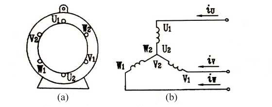 As shown in the Figure (b) above, it is assumed that when the instantaneous value of the current is positive, it flows in from the first ends of each winding and flows out of the tail ends. On the contrary is when the current is negative value.
As show in the Figure (c), when ωt=0, iu=0, the value of iv is negative and iw is positive. Then, the current of phase V flows in from V2 and flows out of V1, whereas W-phase currentflows in from W1 and out of W2. According to Ampere's right-handed rule, the direction of the composite magnetic field produced by the three-phase current can be confirmed the instant ωt=0, as shown in figure (d) ① below. It can be seen that the composite magnetic field is a pair of poles and the direction of the magnetic field is consistent with the direction of the longitudinal axis, that is, the top is the North Pole and the bottom is the South Pole.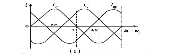 At ωt=π/2, after a quarter of a cycle, the value of iu changes from the zero to maximum, and the current flows in from the first end U1 and outflow the end U2. The iv value is still negative, so the direction of V-phase current is the same as shown in figure ①. iw also becomes negative, and thus W-phase current is W2 inflow and W1 outflow. The composite magnetic field’s direction is shown in the figure (d) ② that the magnetic field direction rotates clockwise 90°compared with the one when ωt=0.
Using the same analytical method, the magnetic fields can be plotted when ωt=π, ωt=2/3*π, and ωt=2, as shown in (d) ③ ④ ⑤ respectively. It is obviously seen from the figure that the magnetic field direction gradually rotates clockwise, totally 360°, that is, a cycle of rotation.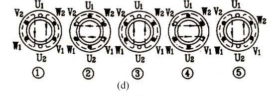
It can be concluded as follows: the three-phase windings are placed in the stators of three phase AC induction motor in the same structure but in the spatial position with 120 degree electrical angle difference from each other. As they are separately supplied with the three phase AC, the composite magnetic field generated between the stator and rotor rotates along the inner circle of the stator, which is called as the rotating magnetic field.
Direction of rotating magnetic field
It is shown in the above figure that three phase AC changes in the U-V-W phase sequence, thus the generated rotating magnetic field rotates clockwise in the space. If arbitrarily switching the current phase sequence of two phase windings of the motor, such as U-W-V, it is practically proved that the generated rotating magnetic field should rotate in the CCW direction. In conclusion, the direction of rotating magnetic field depends on the phase sequence of the three-phase AC power supply in the winding. As long as the phase sequence of the motor is arbitrarily switched, the direction of the rotating magnetic field can be changed.
Speed of rotating magnetic field and slip
The above is based on 2-pole motorf for illustration. If you want to obtain a 4-pole magnetic field, the number of the coils will be double, as shown in the figure (a) and (b) below. According to the above analytical method, the diagram of 4-pole rotating magnetic field in the space is shown in the figure (c). Comparing the rotation speed of magnetic field in the figure (c) with the one in the figure (d) as mentioned above, it is not hard to find that the speed of magnetic field is not only related to the frequency of the power but also the number of poles. 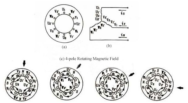
Therefore, the speed of rotating magnetic field is calculated by: n1 = 120f1 / P, where is:
- n1 - the speed of the rotating magnetic field in rev / min
- f1 - the frequency of the three-phase AC supply in Hertz
- P - the number of poles
Rotating magnetic field speed (n1) is also known as synchronous speed. Three-phase induction motor rotor speed (n) will not be accelerated to the rotating magnetic field speed (n1). Only in this way will there be a relative movement between the winding and rotating magnetic field to cut magnetic lines. Thus the induced electromotive force and current can be generated in the rotor winding conductor, then producing the electromagnetic torque to make the rotor rotate continually along with the direction of the rotating magnetic field. It is can be seen that n ≠n1, and n <n1, is a necessary condition for induction motor working, where the name “asynchronous motor” is derived from. The difference between them is called “slip”, which is expressed by the ratio between the difference and the synchronous speed: s = (n1-n)/ n1.
