Voltage Stabilizer Circuit Diagram Analysis
Voltage stabilizer is a power supply circuit or power supply device that can automatically adjust the output voltage. Its function is to stabilize the voltage of the power supply that fluctuates greatly and does not meet the requirements of electrical equipment within the set value range. The purpose of voltage stabilizer is to enable various circuits or electrical equipment to work normally under the rated operating voltage.
Large-scale voltage stabilizers of tens or even hundreds of kilowatts are used to supply the working power of large-scale experimental equipment. There are also small AC voltage stabilizers of several watts to several kilowatts that provide high-quality power for small laboratories or home appliances.
At the very beginning, the voltage stabilizer stabilized the voltage through the beating of the relay. When the voltage of the grid fluctuates, the automatic correction circuit of the voltage stabilizer will be activated to activate the internal relay and force the output voltage to remain close to the set value. The advantage of this circuit is that the circuit is simple, but the disadvantage is that the voltage regulation accuracy is not high, and every beat and shift of the relay will cause an instantaneous interruption of the power supply and spark interference.
This will cause great interference to the reading and writing of computer equipment, and it is easy to cause wrong signals in the computer. In severe cases, the hard disk will be damaged.
The current high-quality small voltage stabilizers mostly use the method of motor-driven carbon brushes to stabilize the voltage. This kind of voltage stabilizer has little interference to electrical equipment, and the voltage regulation accuracy is relatively high. It is a product without waveform distortion.
Analysis of Voltage Stabilizer Circuit Diagram
The voltage stabilizing circuit of the power supply is composed of power transformer T3, rectifier diodes VDl-VD4, filter capacitor Cl-C3 and three-terminal voltage stabilizing integrated circuits ICl and IC2.
The input comparison circuit is made up of resistor Rl, potentiometer RPl-RP9, capacitor C6-Cl4, and Nl-Ng inside the operational amplifier integrated circuit lC3-1C5.
The code control circuit is composed of not-gate integrated circuit IC6-1C8, gate and not-gate integrated circuit IC9, IClO glaze diode VD8-VDl5, resistor R4-R11, capacitor Cl5-C22.
The compensation output circuit is composed of electronic switch integrated circuits ICl (Sl-S4), IC17 (S5-S8), thyristors VTl-VT8, compensation main transformer Tl, compensation auxiliary transformer T2, AC contactor KM, voltmeter PV, and ammeter PA.
The over-voltage/under-voltage protection circuit is composed of the not-gate D9 in IC7, diodes VD5-VD7, resistors R2, R3, transistor V and relay K.
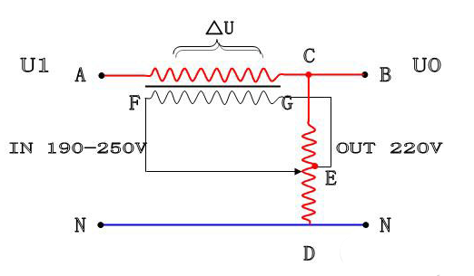
The relatively simple AC 220V voltage stabilizer can use an electronic detection and mechanical adjustment. By comparing the 220V step-down and rectified DC voltage with the standard voltage obtained by the integrated circuit of voltage stabilizer, it can be found that when the 220V power supply voltage is low, the rectified output DC voltage is relatively low compared to the standard voltage. If the triode switch circuit is driven to make the relay actuate, the contact of the relay causes the regulating motor to rotate forward. Subsequently, the single-phase voltage regulating transformer driven by the regulating motor boosts the power supply voltage until the difference between the DC voltage output by the detection circuit and the standard voltage is less than the conduction voltage of the switching circuit. The relay is released and the boost is over. If 220V is too high, the corresponding switch circuit should be turned on to make the regulating motor reverse and step down.
This method is mainly to detect the drive control circuit. Using different power regulators or transformers can simply change the regulator power. However, the accuracy of this method of voltage stabilization is not high, which can basically reach within about 5%.
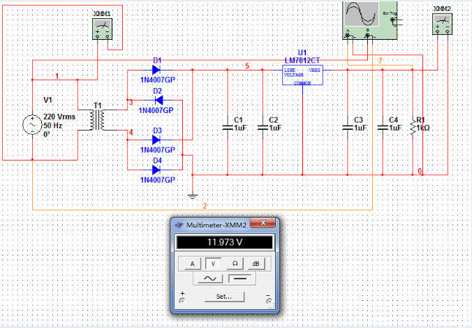
T1 is an AC step-down transformer. If you want to reduce the 220V AC voltage to a lower voltage, for this 12V output linear regulated power supply, it is enough to set the secondary voltage of T1 to 14V~15V.
The rectifier bridge composed of D1, D2, D3, and D4 can convert the AC voltage output by the secondary T1 into a unidirectional pulsating voltage.
C1 and C2 are input filter capacitors, which can convert the unidirectional pulsating voltage into a DC voltage with a small amount of ripple. In addition to ripples, this DC voltage will also change with the fluctuation of the grid voltage, which is unstable.
C3 and C4 are output filter capacitors, their main function is to suppress the self-excited oscillation that 7812 may produce, so as to ensure its normal operation.
