3 Types of Rectifiers
Electroplating is an electrolytic process. The performance, type, and characteristics of the power supply will certainly have an important impact on the electroplating process. Especially in today's rapid development of modern plating technology, the electroplating power supply has a more important position. Therefore, it is necessary to understand the influence of the electroplating power supply on the plating process.
Traditional silicon rectifier
Silicon rectifier has a long history of use and mature technology and is the mainstream product of rectifier.
- Rectification circuit
Industrial production generally uses three-phase regulator voltage regulation, 50Hz three-phase plating rectifier. Various rectifier circuits are obtained by pulsating DC, not pure DC, more or less containing AC components. To compare the amount of pulsating components, the ripple coefficient can be used to express, its meaning is the percentage of AC components in DC components, the smaller the value, the fewer AC components, the closer to pure DC.
Various rectifier circuits have different ripple coefficients. Its order from large to small: three-phase half-wave rectification, three-phase full-wave bridge rectification, or six-phase double inverse star rectification with the balanced reactor. The latter works with rectifier elements in parallel, the waveform is the smoothest, the rectification efficiency is higher, the work is also more reliable, when the most commonly used one.
To obtain low ripple output, it is necessary to use filtering or other special measures. The use of capacitors, inductive energy storage components for filtering, is a common measure to change the pulsating DC into a smoother DC. However, in practice, in addition to small rectifiers for testing, industrial production is not filtered. Special circumstances can use large inductors. Capacitance is not suitable for filtering in the case of low voltage and high current. Capacitive filtering, for industrial frequency rectification, is only suitable for a very small power rectifier power supply. For example, the output 10A single-phase full-wave rectifier, to achieve low ripple output, the filter capacitor should reach 0.1F or more. As the frequency increases, the required capacitance decreases.
The SCR is used to adjust the output average DC size of the common SCR rectifier by changing the conduction angle of the SCR tube, the output of the SCR tube is an intermittent pulse wave, the ripple coefficient is controlled by the conduction angle, the output ripple coefficient is greater than the common silicon rectifier circuit. Especially in the case of using a current lower than the rated current is larger, the output waveform pulsation coefficient is greater.
It uses an industrial frequency transformer to transform the AC input voltage into a lower (10V to 20V) AC voltage and then rectifies and regulates the voltage through the SCR. The control mechanism is through the control circuit to control the conduction angle of the SCR to achieve the output voltage and current regulation. The disadvantages of this kind of power supply are large size, heavyweight, noise, power consumption, and ripple. With the increasing requirements of the production process for coating quality and automatic control, as well as people's awareness of energy saving and environmental protection, it has been gradually eliminated in PCB plating. It is mainly used in industrial plating with higher current.
- Types of rectifier elements
The rectifier element is commonly known as the diode. Since all the output current of the rectifier has to pass through the rectifier element, it can be said to be the heart of the rectifier. Rectifier element is divided into silicon rectifier element and silicon controlled rectifier element two kinds. Chrome-plated rectifiers mainly use silicon rectifier elements. Although silicon-controlled technology has developed considerably, and the application on the plating is increasing, but I still recommend the use of a silicon rectifier. The main reason is the waveform problem. The silicon-controlled rectifier is used to control the rectifier on time and cut-off time to control the current. Rectifier waveform is good when used at full load. But when the output current is small, the current waveform becomes worse. The smaller the current, the worse the waveform. The output current size of the silicon rectifier has almost no effect on the waveform.
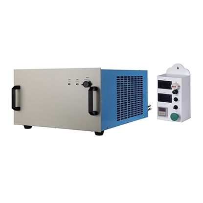
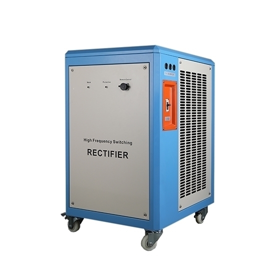
High-frequency switching rectifier(switching power supply)
A new type of electroplating power supply equipment - high frequency switching power supply. It has the advantages of the smooth waveform of silicon rectifier and convenient voltage regulation of silicon controlled rectifier, the highest current efficiency (up to 90% or more), the smallest size, is a promising rectifier. Manufacturing technology has solved the power problem, thousands of amps to tens of thousands of amps of high-power switching power supply has entered the practical stage of production.
It will be AC power grid by EMI anti-electromagnetic interference line filter, direct rectification, filtering, DC voltage conversion by the converter into tens or hundreds of kHz of a high-frequency square wave, isolated by high-frequency transformer, step-down, and then by high-frequency filtering output DC voltage. After sampling, comparison, amplification, and control drive circuit, control the duty cycle of the power tube in the converter to get a stable output voltage (or output current).
The regulator tube of high-frequency switching rectifier works in switching state, with small power loss, efficiency can reach 75%~90%, small volume, and lightweight, and the accuracy and ripple coefficient is better than silicon rectifier, and the accuracy required by production can be achieved in the full output range. It has self-protection capability and can start and stop at will under the condition of carrying the load. It can be easily connected with a computer, which brings great convenience to automatic production and is widely used in the PCB plating industry.
The main conversion structure of high-frequency switching rectifiers for electroplating is forward-excited, half-bridge, full-bridge, etc. There are both pulse-width modulation (PWM) "hard-switching" circuits and the popular phase shift control "soft-switching" power circuits.
Using voltage or current feedback control, pulse-width modulation (PWM) high-frequency switching rectifier, operating frequency mostly below 50 kHz. It is through the interruption of power flux and adjust the duty cycle method, change the width of the drive voltage pulse to adjust the output current, so that the device works in the "hard switching" state, that is, forced on (when the voltage is not zero) or forced off (when the current is not zero), so that the switching power tube switching period at the same time there is a high voltage and high current cross, so Large switching losses and strong spike interference. Transformer leakage inductance and the high current rate of change excited by the high voltage spikes, not only easy to damage the power tube, but also produce significant electromagnetic radiation, reducing the reliability and power supply efficiency.
Switching power supply its frequency has reached audio, through the filter to achieve low ripple output is much easier to implement. And current stabilization, voltage stabilization, and other functions are more easily achieved.
Pulse power supply equipment
With the development of power electronics science and technology, plating rectifiers are being developed from a single function to a multi-function. As the pulse power supply is mainly controlled by embedded single-chip computers, etc., so in addition to the realization of pulse output, generally has a variety of control functions.
- Automatic current and voltage stabilization.
Traditional silicon rectifier current or voltage can not be automatically stabilized, fluctuating with the fluctuations of the grid voltage. The pulse power supply has a high-precision automatic regulation function. If the three-phase voltage fluctuations in the grid up to hundreds of volts, the pulse power output voltage can be almost unchanged. The automatic regulation of the pulse power supply generally has two modes.
- Constant current-voltage limit mode. When the plating process parameters, such as the part area, temperature, concentration, acidity and alkalinity, and other process conditions change, the conventional rectifier current will fluctuate. In the constant current mode, the output current is automatically constant at the set value and does not change. This is useful in cases where a precise calculation of hard chrome thickness is required. The purpose of the voltage limiting function in the constant current mode is to protect the equipment from burnout.
- Constant voltage current limiting mode. When the plating process parameters are changed, the output voltage is automatically constant at the set value without changing. This mode is not often used for hard chrome plating, but it is useful for aluminum oxide coloring.
- Multi-stage operation mode
Aluminum anodizing or hard chrome plating often requires reverse electrolysis, high current impact, step feeding, etc. The conventional power supply can only be achieved manually. The pulse power supply with multi-stage operation mode only needs to be set in advance and can be automatically adjusted in sequence during production. This feature is very useful for hard chrome plating.
- Two-way pulse function
Positive and negative pulse frequency, duty cycle, and forward and reverse output time can be adjusted independently, which is flexible and convenient to use. With the hard chrome plating process, different physical properties of the plating layer can be obtained.
- DC superposition function
While outputting forward and reverse pulse current, a pure DC component is superimposed by the same power supply, which widens the scope of use and application of pulse power supply.
In recent years, the domestic multi-functional pulse power supply technology has become mature, in which the pulse waveform vertical degree, waveform smoothness, stability, anti-interference, and other indicators reach or even exceed the foreign level.
DC power waveform has a prominent impact on the quality of electroplating, for example, high frequency fixed pulse width high-frequency voltage/stable current pulse power plating will produce special effects, which is also the effect of ordinary DC power plating can not be achieved, some phenomena can not be explained by conventional electrochemical theory. The effect of DC waveform on plating deposition is difficult to predict theoretically, but only through a large number of experiments to make a relative comparison and filter out the appropriate waveform.
In recent years, the new zero voltage conversion (zvT) and zero current conversion (ZCT) technology, or "soft switching" technology, a combination of the advantages of both PWM switching and resonant conversion technology: both pulsed square wave efficient power transfer and constant frequency control to optimize parameters, but also the resonant technology of low loss and zero voltage conversion. characteristics of resonant technology. This "zero-switching" technology makes full use of the resonance between the leakage inductance of the transformer and the output junction capacitance of the power tube to produce the conditions of zero-voltage conduction and zero-current cutoff, where the voltage is zero when the switch is on and the current flowing through the switch is zero when it is cut off. Therefore, it greatly reduces the switching voltage, current stress, and spike interference of the power tube, reduces the power consumption, and significantly improves the switching efficiency.
