7 Steps to Install Plating Rectifier Safely
Plating rectifier is a rectifier power supply, which is simply a device that converts AC to DC. It has two main functions: First, it converts AC power to DC power and supplies it to the load after filtering, or to the inverter. Second, it provides charging voltage to the storage battery. Therefore, it also plays the role a charger at the same time.
ATO explains the installation steps of high-frequency electroplating rectifiers for you, so that you can install the rectifier correctly, and operate directly after you turn on the power.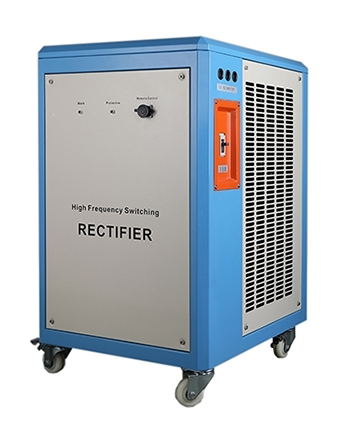
Step 1: Fix the plating rectifier
It is recommended to fix the plating rectifier near or above the plating tank plate, so that you will have convenient operation in the future.
Step 2: The distance between the plating rectifier and the plating tank
In order to ensure that the pulse current waveform is not distorted and has a small attenuation when it is introduced into the plating tank, the distance between the plating rectifier and the plating tank is preferably 2-3m during installation, otherwise the impact on the trailing edge of the pulse current waveform is large and the plating will not achieve the expected effect.
Step 3: Connect to the positive and genative anodes of the output
The connection method of the DC power cord is not suitable for the connection of plating rectifier. For the output connection of the plating rectifier, it is expected that the inter-electrode capacitance of the two wires can offset the transmission inductance effect of the wires. Therefore, the best method for the cathode and anode wires is to cross them in twist and lead to the side of the plating tank to keep the pulse waveform unchanged. You can connect the prepared positive and negative electrodes to the output positive and negative positions at the back of the high-frequency plating rectifier. The stainless steel screws are suggested to be used for fixing.
Step 4: Wire selection
Because the rectifier is a pulse power source, in order to avoid skin effects, multiple conductors should be selected as the connecting line between the rectifier and the plating tank when the conductor is selected, because the line capacitance of the multiple-strand twisted wire can offset its inductance effect.
The specifications of the wire must meet the rated current it passes, because the current density of the pulse current is much larger than the average current density. Therefore, the current thermal effect of the current that can withstand the pulse power must be considered to ensure that the attenuation from the pulse power source to the plating tank is the lowest.
Step 5: Connect to the filter, wag machine, heating pipe and other equipment
If your customized high-frequency plating rectifier has these functions, please connect the corresponding equipment to the terminal block behind the high frequency plating rectifier. The terminal block has the corresponding identification, you just need to connect according to the identification. If the rectifier customized by you does not have these features, please ignore this step.
Step 6: Connect to the power line of the plating rectifier
It is recommended to use a fixed connection to connect the power line of the plating rectifier to a power source (380V or 480V, which is determined by the input voltage of your high-frequency plating rectifier). It is not recommended to use a socket connection. In performing this step, be sure to turn off the power to ensure safety.
Step 7: Turn on the power supply.
After confirming that the high-frequency plating rectifier is installed correctly, it can be operated by turning on the power supply only.
