Flow Switch Function Testing
Flow switches are often used to monitor the flow rate of water. Once the water stops flowing through it, the flow switch will instantly trigger a series of actions within a system, such as activating an alarm, so as to ensure the safety of downstream equipment. Flow switches are usually found in water cooling equipment and other similar large equipment or machines.
The absence of water flow through the cooling pipe can result in rising temperature of the equipment and the downstream units will not work properly or even burn out. Flow switches are usually found in water cooling equipment and other similar large equipment or machines. If there is no water flowing through the cooling pipe, the temperature of the equipment will rise accordingly, which then may lead to the improper working or even burnout of downstream units.
For this reason, it's essential to install a flow switch in the pipeline of the water-cooling system. Once the magnetic water flow switch detects no water flowing through, it will trigger an alarm signal in order to avoid accidents. Followed is a simple application demo of the magnetic water flow switch from ATO.
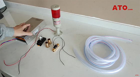
Things needed include a magnetic water flow switch, a water pipe, pagoda joints, DC power supply, a relay and a warning light.The working mechanism of the system is explained as follows.
 The water flowing through the plastic valve core enables the onboard permanent magnet to approach the transducer on the external black switch for the purpose of sending signals. When there is no water flow or there is obstruction that stops water flowing through the switch, the two magnets located inside the flow switch will produce a repulsive force which serves to reset the switch. To put it simply, whether there is a signal output from the flow switch depends on whether there is water flow through the switch, and this is the working mechanism of the NO switch.
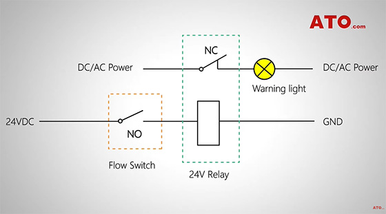
To realize the function of the magnetic water flow switch necessitates the arrangement of the control circuit. As shown in the demo, connect one end of the magnetic water flow switch to the positive pole of the DC power supply, and connect the other end of the switch to the positive terminal of the relay coil, then join the coil's negative terminal to the COM (GND) port of the supply. The on-off of the warning light is controlled by the NC contacts of the relay. That is to say, the warning light goes out when the relay is connected, and the warning light is on when the relay is disconnected.
The magnetic water flow switch from ATO features G1/2" of joint size at both ends. Here we prepare two pagoda joints for the ease of joining up the water pipe and the switch. With the water pipe part done, we can join together the magnetic water flow switch and other necessary components according to the control circuit diagram. The on-off of the relay is controlled by the magnetic water flow switch. The warning light is controlled by the normally closed contacts of the relay.
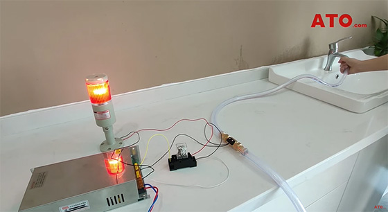
The wiring is complete. With every thing is done, we can power on the system for trial. It can be seen that when there is no water flow through the water pipe, the magnetic water flow switch is triggered, and the relay turns on the warning light.
If you want to know more about flow switch, please click this video.
