How to Build a Constant-Pressure Pump with GK3000 VFD?
This guide explains how to build a constant-pressure pumping system using the upgraded GK3000 Variable Frequency Drive (VFD) from ATO. The system adjusts pump motor speed based on real-time pressure feedback to maintain stable output pressure while improving energy efficiency and reducing mechanical wear.
Compared with earlier configurations, this setup uses an external 24VDC switching power supply to power the level sensor independently. This isolates the sensor from the VFD’s internal supply, improving signal stability and measurement reliability for applications requiring precise pressure control.

Components
- Upgraded GK3000 VFD
- Two-wire submersible level sensor (4-mA)
- Self-hold push button
- 3-phase induction motor
- Switching power supply
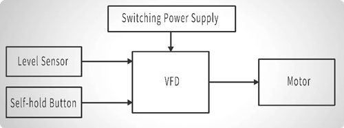
I. System Working Principle
The key control logic of the system is as follows. The external 24V power supply is used to provide stable power to both the sensor and the VFD control inputs, ensuring reliable signal transmission and consistent system operation. The self-hold push button is responsible for controlling the start and stop of the VFD constant-pressure function, allowing the system to be manually enabled or disabled as required. Based on the 4–20mA signal received from the sensor, the VFD continuously adjusts the pump motor speed, increasing or decreasing output as needed to regulate and maintain stable water pressure throughout system operation.
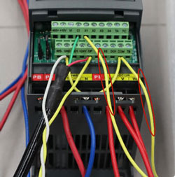
II. Wiring Breakdown
Proper wiring is essential to ensure safe operation and accurate control of the constant-pressure system. The wiring can be divided into three functional sections: power and motor connections, sensor integration, and control input wiring.
1. Power Connection
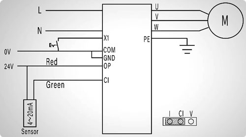
Connect the L and N wires to the VFD power input terminals, ensuring the PE is properly grounded. Proper grounding is essential not only for safety but also to minimize electrical noise that could affect sensor readings and VFD operation.
2. Motor Connection
Connect the motor phases U, V, and W to the corresponding VFD output terminals. This connection allows the VFD to precisely control motor speed and torque in response to the feedback signal from the pressure sensor.
3. Level Sensor Integration
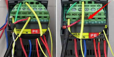
This step is the most critical. When using an external 24VDC power supply for the sensor, it is mandatory to remove the factory-installed jumper between the 24V and OP terminals on the VFD. This prevents interference from the VFD’s internal 24V output and ensures stable, reliable sensor readings.
Make the connections as follows:
- Connect the external power supply by wiring its 24V output to the VFD OP terminal and the sensor red wire, and its 0V terminal to the VFD GND terminal.

- Short GND to COM to unify the reference ground for all input signals.
- Set the analog input jumper to CI–I, selecting the 4–20mA current input mode for the VFD.
- Connect the sensor green wire to the CI terminal on the VFD. This ensures that the VFD receives accurate pressure feedback, allowing the system to maintain the target pressure reliably.
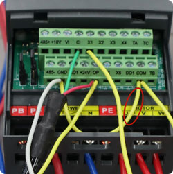
4. Physical Wiring
Finally, connect the self-hold push button between the VFD terminals X1 and COM to serve as the manual start/stop control for constant-pressure operation. Once this connection is completed, all physical wiring for the system is finished and the setup is ready for parameter configuration and testing.
III. Parameter Settings
With the physical wiring completed, the next step is to configure the GK3000 VFD parameters to enable constant-pressure operation. Follow the steps below carefully to ensure accurate and reliable system performance.
1. Enable Constant-Pressure Mode
- Press the MENU button and navigate to parameter group P0.
- Enter P0.01 and set it to 10 to enable constant-pressure control mode.
- Move to P0.03 and set it to 1 to allow the VFD to accept RUN commands from the digital input terminals.
2. Configure PID Feedback
- Navigate to parameter group P6.
- Set P6.02 = 1 to select the CI terminal as the PID feedback source.
- Set P6.06 = 0.01, which defines the proportional gain for the PID loop. This value determines how quickly the VFD responds to deviations from the target pressure, balancing responsiveness and stability.
3. Set Target Pressure and Safety Limits
- Locate P6.30 and enter the desired target pressure (e.g., 0.07 MPa). The VFD will maintain this pressure automatically.
- Set P6.31 = 1.0 to define the maximum allowable pressure, protecting the system from overpressure.
- Set P6.32 = 0.005 to define the minimum pressure limit, ensuring safe operation at low flow or demand conditions.
4. Configure Sleep/Wake Logic
- Set P6.35 = 0.8, which defines the wake threshold at 80% of the set pressure.
- Set P6.36 = 2 s, the wake delay, ensuring the VFD only restarts the pump after the low-pressure condition persists for 2 seconds.
- Set P6.37 = 1.0, defining the sleep threshold at 100% of the set pressure.
- Set P6.38 = 5 s, the sleep delay, to ensure the system stabilizes at the target pressure before entering sleep mode.
- Finally, set P6.41 = 11 to activate the sleep/wake logic based on the pressure percentage.

Important Note: After completing all parameter settings, if you return to P0.01 = 10, the VFD may automatically reset P6.30 (target pressure) to a default value (e.g., 0.5 MPa). In this case, simply re-enter your desired target pressure (e.g., 0.07 MPa) to ensure proper operation.
IV. Test Run
With all wiring and parameter settings completed, the system is ready for testing and operational verification. The following steps illustrate how to monitor and operate the GK3000-based constant-pressure pumping system.
1. Monitor System Parameters
Navigate to b0.46 to view the Target Pressure, which represents the setpoint the system is designed to maintain, and to b0.47 to monitor the real-time feedback pressure from the level sensor, providing continuous insight into overall system performance and operating status.
2. Adjust Target Pressure (Optional)
At this stage, the target pressure (P6.30) can be adjusted live using the Up/Down keys on the VFD interface, within the safety limits defined by P6.31 (maximum) and P6.32 (minimum). This allows fine-tuning of system behavior during the initial test or commissioning.
3. Start Constant-Pressure Mode
Press the self-hold push button to activate constant-pressure operation. The VFD ramps up the motor gradually according to the PID control logic, ensuring smooth acceleration and avoiding sudden pressure surges.
4. Sleep Mode Activation
When the feedback pressure reaches 100% of the setpoint and remains stable for 5 seconds, the VFD automatically enters Sleep Mode, stopping the motor to conserve energy and reduce wear on the pump.
5. Monitoring During Sleep
While in Sleep Mode, the real-time pressure can still be observed via b0.47, providing confirmation that the system maintains pressure within safe limits even when the motor is stopped.
6. Automatic Wake-Up
If the system pressure drops to 80% of the target and remains below this threshold for 2 seconds, the VFD automatically restarts the motor. The pump then restores pressure to the setpoint efficiently.
7. Continuous Operation Cycle
Once pressure reaches 100% of the target and remains there for 5 seconds, the VFD returns to Sleep Mode. This cycle of automatic wake-up and sleep continues indefinitely, maintaining stable pressure while optimizing energy consumption and extending the service life of the pump and motor.
This completes the basic operating cycle of the constant-pressure control system. Through continuous monitoring and automatic adjustment, the system ensures reliable performance under varying load conditions, providing both efficiency and durability for water supply and pressure-boosting applications.
V. Summary
The GK3000-based constant-pressure pumping system delivers precise and stable pressure control by dynamically adjusting motor speed based on real-time sensor feedback. Its integrated sleep and wake logic enhances energy efficiency by reducing unnecessary pump operation, while also prolonging the service life of the motor and associated equipment. This system provides a practical and reliable solution for residential, commercial, and industrial water supply or pressure-boosting applications, ensuring consistent performance under varying load conditions. For additional technical support, guidance on installation, or product information, users are encouraged to visit the ATO.com.
