How to Build a Constant Pressure Water System Using the GK3000 VFD?
A constant-pressure water supply system is essential for applications where stable water pressure directly affects performance and reliability. In traditional pump systems, fixed-speed motors or manual valve adjustments often lead to pressure fluctuations, higher energy consumption, and increased mechanical wear. By using the GK3000 upgraded Variable Frequency Drive with built-in PID control, a fully automated pump control solution can be implemented. Combined with a pressure sensor, the system automatically regulates pump speed to maintain stable water pressure under varying load conditions. This article provides a complete guide to the system architecture, wiring method, parameter configuration, and commissioning process for a GK3000-based constant-pressure water supply system.
I. Major Equipment
- VFD GK3000 (Upgraded Ver): Acts as the core controller, performing PID calculations and adjusting motor frequency in real time.
- Two-wired Submersible Level Sensor (4–20mA ): Continuously monitors pipeline pressure and sends feedback to the VFD.
- Three-phase Induction Motor: Driven by the VFD to control flow rate and pressure.
- Self-Hold Push Button: Used for local start and stop control.
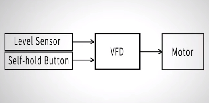
II. Working Principle
- The pressure sensor measures real-time system pressure
- A 4–20mA signal is sent to the VFD analog input
- The VFD compares actual pressure with the setpoint
- Output frequency is automatically adjusted
- Pump speed changes dynamically to maintain constant pressure
The system operates as a closed-loop PID control system. This control method ensures smooth operation, fast response, and improved energy efficiency.
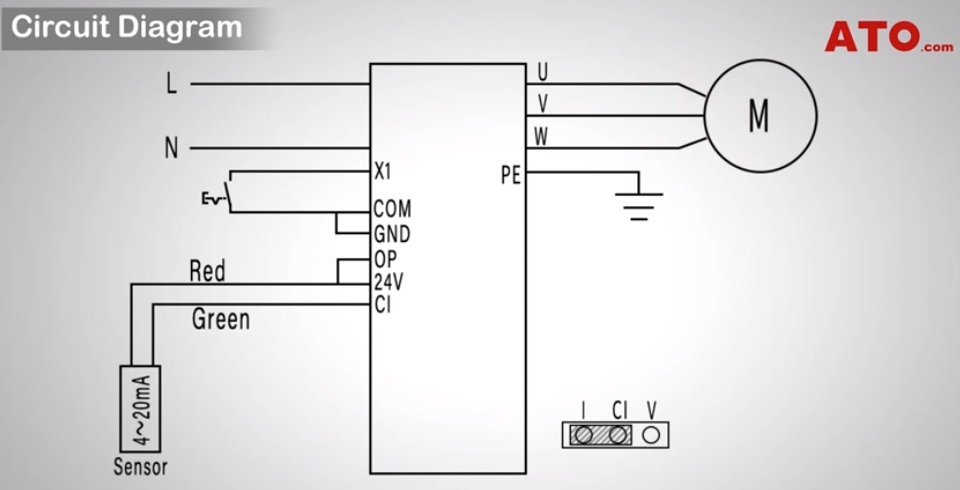
III. Wiring Method
1. Power Supply and Motor Wiring
- Connect Live (L) and Neutral (N) to the VFD power input
- Connect the PE terminal to protective earth
- Wire the pump motor phases to the U, V, and W output terminals
2. Pressure Sensor Wiring
The VFD GK3000 upgraded Ver includes an internal 24VDC power supply, allowing direct connection of a two-wire pressure sensor.
- Red wire: Connect to +24V and OP terminals
Keep the factory-installed jumper to enable sensor power - Green wire: Connect to CI (Current Input)
Receives the 4–20mA pressure feedback signal
Important Note: Ensure the VFD analog input jumper is set to current (I) mode, not voltage mode, to correctly process the 4–20mA signal.
3. Start/Stop Button Wiring
- Connect the self-hold push button between X1 and COM
- Enables external run/stop control of the VFD
IV. Parameter Configuration
1. Basic Operation Parameters (P0 Group)
- P0.01 = 10
Enable constant pressure control mode - P0.03 = 1
Run command source: external terminal
2. PID and Feedback Parameters (P6 Group)
- P6.02 = 1
Feedback source: CI terminal - P6.06 = 0.01
Proportional gain (P value), recommended to start low for stability
3. Pressure Setpoint and Protection Limits
- P6.30 = 0.07 MPa (example set pressure)
- P6.31 = 1 MPa (maximum pressure limit)
- P6.32 = 0.005 MPa (minimum pressure limit)
4. Sleep and Wake Functions (Energy Saving)
- P6.35 = 0.8: Wake-up threshold at 80% of set pressure
- P6.36 = 2 s: Wake delay to prevent false triggering
- P6.37 = 1: Sleep condition at 100% of set pressure
- P6.38 = 5 s: Sleep delay to reduce frequent cycling
- P6.41 = 11: Disable frequency-based sleep conditions so control depends only on pressure feedback
Tip: If the pressure setpoint resets after changing operation mode, simply re-enter P6.30.
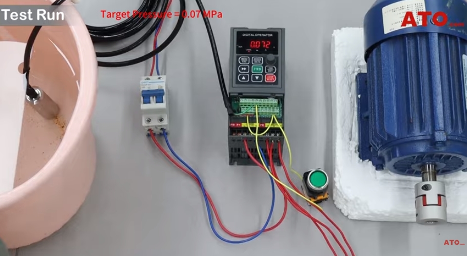
V. System Testing and Operation
After completing wiring and parameter setup, the system can be tested:
- b0.46: Displays the pressure setpoint
- b0.47: Displays real-time pressure feedback
Operating Logic
- Press the start button to activate constant pressure mode
- Pumping accelerates smoothly until the pressure reaches the setpoint
- After maintaining target pressure, the system enters SLEEP mode
- When pressure drops below the wake threshold, the VFD automatically restarts the pump
- Once pressure stabilizes again, the system returns to sleep
This automatic cycle ensures stable pressure with minimal energy consumption.
VI. Applications and Benefits
A GK3000 VFD-based constant-pressure water supply system offers:
- Stable and consistent water pressure
- Automatic pump speed control with PID regulation
- Reduced energy consumption and mechanical wear
- Simplified wiring using internal 24VDC sensor power
This solution is widely used in booster pump systems, irrigation, aquaculture, residential water supply, and small industrial circulation systems.
VII. Conclusion
This article detailed how to set up a constant-pressure water supply system using the GK3000 upgraded VFD, covering the entire process from system architecture and wiring to PID configuration and testing. By integrating the GK3000 VFD with a 4–20mA pressure sensor, the system automatically adjusts pump speed to maintain stable water pressure and significantly reduce energy consumption.
For detailed wiring and step-by-step operation, please watch the video below. If you are planning to build or upgrade a constant pressure pumping system, ATO Store offers a full range of compatible products, including GK3000 VFDs, Induction Motors, More Level Sensors & Transmitters, and Self-Hold Push Buttons. All products are carefully selected for reliable performance and easy integration. Visit our store to explore more solutions and select the right components for your application. We look forward to helping you build a more efficient, stable, and energy-saving water supply system.
