How to Test a Transformer?
Transformer is a device that uses the principle of electromagnetic induction to change the AC voltage. A step up transformer is a type of transformer that increases the voltage of the input power. This means that the output voltage is higher than the input voltage. A step down transformer is a type of transformer that decreases the voltage of the input power. This means that the output voltage is lower than the input voltage.
Whether troubleshooting a power transformer or replacing one, knowing how to test a transformer is an integral part of the process. The three primary tests used to determine the condition of a transformer are the open-circuit test, short-circuit test, and measurements of winding resistance. In this atricle, ATO industrial automation will introduce 3 methods of testing transformer.

Open-circuit Test:
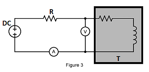
The connection setup for the open-circuit test for a step up and down transformer is shown in Figure 1. The various components used are: autotransformer, voltmeter, wattmeter, ammeter and transformer under test. An autotransformer is a special type of transformer with a single winding and is highly effective in producing a regulated voltage. The output of an autotransformer can be tapped at various points to produce varied voltages. The autotransformer is connected to an AC voltage source, as seen in Figure 1. The output of the autotransformer is tapped and connected to the ends of a voltmeter.
Then perform the following steps:
- Keep the secondary side of the power transformer under test open-circuited.
- Slowly increase the applied voltage at the primary side till it reaches the rated voltage of the transformer. Keep checking the voltmeter during this phase.
- Once the rated voltage is reached, record the readings of all three instruments, namely, voltmeter, ammeter, and wattmeter.
The ammeter gives the value of no-load current (as the secondary side is left open-circuited). The voltmeter reading is equal to the voltage induced on the secondary side of the transformer. The wattmeter reading gives the value of input power during the test. As the transformer is open-circuited, there is no current flow on the secondary side. Hence, the wattmeter reads the magnitude of core losses and copper losses occurring in the transformer. The no-load current is much less compared to the full-load current of the transformer. Hence, the copper loss due to the no-load current can be neglected. Therefore, an open-circuit test gives the magnitude of core losses within the step up transformer. The core loss magnitude can be used to determine if there are any issues within the magnetic core of the transformer.
Short-circuit Test:
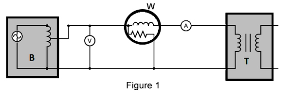
The various components used are: autotransformer, voltmeter, wattmeter, ammeter, transformer under test. Perform the following steps to test the transformer:
- Short circuit the secondary side of the 110 to 220 transformer.
- Apply a low voltage of 7-10 % of the transformer's rated voltage at the primary side with the help of an autotransformer (Figure 2 labeled B). The output of an autotransformer can be tapped at various points to get different voltages.
- Slowly increase the applied voltage until the ammeter (Figure 2 labeled A) and wattmeter (Figure 2 labeled W) give a reading equal to the transformer's rated current.
- Note the readings on the voltmeter, ammeter, and wattmeter.
The ammeter reading gives the primary side equivalent of the step up and down transformer's full load current. As the applied voltage is very small compared to the rated voltage of the transformer, core losses can be taken as negligible. Therefore a short-circuit test measures the copper loss in a transformer. The value of copper loss can be used to determine if there is an issue with the step down transformer windings.
Resistance Measurement:
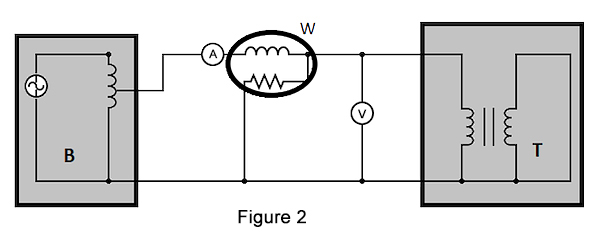
Measurement of a transformer's winding resistance is essential to calculate the I2R losses in the transformer. The resistance value can also be used as a measure to diagnose possible damages..
The various components used are: transformer under test, voltmeter, ammeter, DC voltage source. A simple method to measure the power transformer resistance is shown in Figure 3: