Temperature Transmitter Calibration
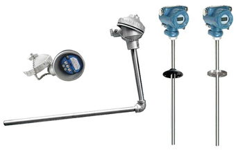
Temperature sensor equipped for the temperature transmitter can be divided into thermocouple and RTD, and the RTD sensor can be divided into three kinds of 2-wire RTD, 3-wire RTD and 4-wire RTD. Despite the differences mentioned above, measurements and principles of the temperature transmitter are the same. Now the indication error calibrating of ATO-S-TEMPT-ST500 smart temperature transmitter would be taken as the example to analyze temperature transmitter calibration and errors in the process.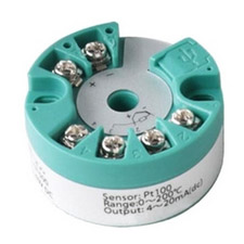
1. Requirements for Standard Devices of Temperature Transmitter
Generally, temperature transmitter calibration can be carried out by the instruction manual of temperature transmitter on the basis of existing devices. But to ensure the debugging quality, there are some requirements for the standard devices used in the debugging. As usual, the error of standard devices should be less than 1/5 of the allowable error of debugged temperature transmitter. And for the 0.1% level temperature transmitter, the error should be less than 1/3 of the allowable error. Moreover, the uncertainty and repeatability of the whole set of standard devices should also meet the requirements.
2. Calibration Method of Temperature Transmitter
- Analog calibration method of temperature transmitter
In the analog calibration method, the standard DC resistance box is used to replace the temperature sensor that connects with the temperature transmitter, and then the resistance value of resistance box is changed to measure the output value of temperature transmitter, thus completing the debugging. Within the range of temperature transmitter, the debugging point should not be less than 5, and the reciprocal cycles should not be less than 3 times. After treating the measurement result, the indication error of temperature transmitter could be calculated. Debugging result of this method is a combination of temperature transmitter and analog signal source. It doesn't include the uncertainty of temperature sensors. Analog calibration method of temperature transmitter is the most commonly used method, it's mainly used to check the head mounted temperature transmitter, passive temperature transmitter and DIN rail temperature transmitter. - Comprehensive Calibration method of Integrated Temperature Transmitter and Temperature Sensor
The comprehensive calibration method is to debug the temperature sensor and temperature transmitter together, it measures the output of temperature transmitter by changing the temperature field of thermostatic equipment, the debugging points and reciprocal cycles are the same to that of the analog calibration method. Then the indication error of temperature transmitter could be calculated. The debugging result of this method is a combination of temperature transmitter and temperature sensor, and this method is mainly used to test the integrated thermocouple temperature transmitter and integrated RTD temperature transmitter with temperature sensor probe.
3. Error Source of Standard Devices
Error sources of standard devices depend on different calibration methods (namely different input signal), and they are described as follows:
Error sources of analog debugging system include:
- Error of DC resistance box.
- Error of electrical measuring instrument (digital voltmeter).
- Influence of DC regulated power supply.
- Accuracy effect of I/V transform resistance.
- Reading errors can be neglected.
Error sources of comprehensive debugging system:
- Error of first-class mercury thermometer.
- Error of electrical measuring instrument.
- Error of uneven temperature field in thermostatic equipment.
- Influence of DC regulated power supply.
- Accuracy effect of I/V transform resistance.
- Error of temperature sensor probe (thermocouple or RTD).
- Errors caused by reading, calculation and response time of temperature measuring elements are negligible.
As the errors are independent, the sum of total uncertainties is calculated by the root of square sum.
4. Conversion Accuracy and Overall Accuracy of Temperature Transmitter
Temperature transmitter manufactures have different methods to express the accuracy level of temperature transmitter, some manufacturers call it conversion accuracy, which is based on the temperature transmitter itself, and the higher accuracy is ±0.1%. Some other manufacturers call it overall accuracy, which is based on the comprehensive error of temperature transmitter and temperature sensor, the higher accuracy is ±0.25%. It is helpful for users to understand the accuracy representation method, so users shall care about the overall accuracy when purchasing a temperature transmitter.
For example: The temperature transmitter has an overall accuracy of ±0.25%. Temperature transmitter is assumed selecting A-level Pt100 RTD, whose allowable deviation is (0.15+0.2%|t|). When the test temperature is 100℃, the maximum allowable deviation can be ±0.35%. But if the overall accuracy is required to be ±0.25%, the zero point and range of temperature transmitter could be adjusted to compensate for the partial linear error of the temperature sensors. In field application, the temperature sensors break frequently, and the overall accuracy is unable to maintain the original indicator after replacement. In order to ensure the original overall accuracy, comprehensive debugging shall be made after replacing the temperature sensors. However, some manufacturers don't recommend users to calibrate the zero point, range and linear randomly, and they hide these potentiometer. On this point, it's more practical for users to express the error with conversion accuracy, and the temperature transmitter calibration should also be based on the conversion accuracy. If protection tube is used in comprehensive debugging, thermal conductivity error shall be considered. The insulation resistance of temperature sensors and metal protection tube shall also be tested, which is generally required to be larger than 100MΩ, otherwise, it will affect the measurement tests or cause interference. Seriously, it will even affect the normal operation of temperature transmitter.

Estoy en la búsqueda de una norma para calibración de transmisor de temperatura. Ustedes disponen.
Saludos
Vanessa