VFD for wire drawing machine
I. Overview
The wire drawing machine is one of the main equipment of the metal wire processing as well as the cable and wire industry. It is mainly used to process the metal wires into the fine lines of various specifications. It usually constitutes the paying off, water cooling, winding up, winding displacement and other components. Its electric drive part is mainly realized by paying-off motor, winding-up motor and winding displacement motor. The wire drawing machine belongs to the constant-torque load. Its characteristics require that the VFD has a big start-up torque and can satisfy the full-load output in low speed. Meanwhile, it requires realizing the coordinated control of several motors in high precision percentage.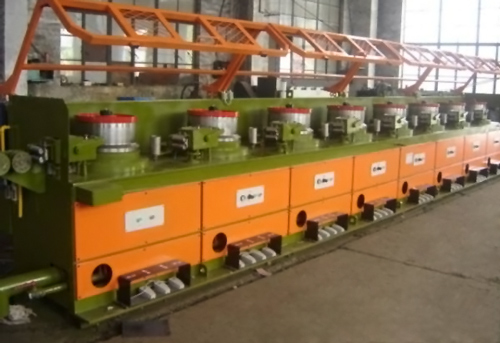
II. Processes of the wire drawing machine
- Wire sending: As to the sending of the metal wire, its control doesn't have too high precision requirement to the whole wire drawing machine link. For the most wire drawing machine, the operation of wire sending is realized through VFD driving the wire sending rack. However, there are also some wire drawing machines controled by double VFDs. Even some are delivered into the wire drawing machine through the drawing of the thread tension in the wire drawing process, thus realize free wire sending.
- Wire drawing: The wire drawing process is the most important working step of the wire drawing machine. The wire drawing diversifies greatly as to different metal products, different wire variety and requirement.
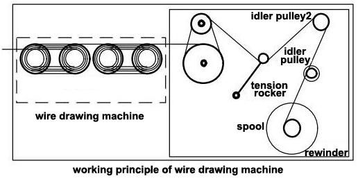
- Rewinding: The working speed of the rewinding link decides the manufacturing efficiency of the entire wire drawing machine. It is also the part which is the most difficult to control in the system. In the rewinding process, the normal control technology is to realize the winding of the metal products through synchronous control and tension control.
III. Solutions
- Feedforward PID control mode is employed between every pass. The main speed is calculated by the second flow of the front and back class metals. PID is acting as the fine tuning quantity of the system speed. The speed calculation is realized inside the VFD. So, it has quick response, low cost and simple debugging.
- Controlling the torque between each pass can be used to distribute the torque current between each VFD accurately, thus realizing the control system of the unstressing arm, simplifying the mechanical design and reducing the system cost.
- The rewinder part adopts PID feedback method, which means to adjust the practical tension through adjusting the air pressure of the swing arm.
- Various linkage logic control of the system is realized through PLD.
IV. Parameter setting of ATO VFD
| Function code | Name | Set value | Remark |
| P0.01 | Frequency setting channel | 5 | Setting channel |
| P0.02 | Value setting of the operating frequency | 70 | Setting value |
| P0.03 | Channel selection of the operating frequency | 1 | Terminal control |
| P0.06 | Maximum output frequency | 70 | Set according to practical condition |
| P0.17 | Acceleration time 1 | 20 | |
| P0.18 | Deceleration time 1 | 20 | |
| P0.19 | Upper limiting frequency | 70 | |
| P4.01 | Terminal selection of the input terminal X2 | 4 | |
| P4.02 | Terminal selection of the input terminal X3 | 17 | |
| P4.03 | Terminal selection of the input terminal X4 | 10 | |
| P4.04 | Terminal selection of the input terminal X5 | 18 |
Buying an ATO VFD for wire drawing machine improvment now, 20 hp VFD, 75 hp VFD, 200 hp VFD...
