Control Transformer Working Principle
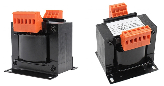
Control transformer is a small dry-type transformer, which is mainly used to change the voltage of AC power. It is wound by an iron core and a coil. It can change not only the voltage of the alternating current, but also the impedance. When the design power is not exceeded, the current can also be changed. In different environments, the transformer also has different applications. Generally, it is used as a control lighting and indicator light source for electrical appliances in machine tools and mechanical equipment.
The control transformer works according to the principle of electromagnetic induction. A transformer has two sets of coils: A primary coil and a secondary coil. The secondary coil is just outside the primary coil. When alternating current is applied to the primary coil, the iron core of the transformer generates an alternating magnetic field, and then the secondary coil generates an induced electromotive force. The primary winding and the secondary winding are commonly covered on the iron core, so that they can be coupled with each other through magnetic circuits and circuit coupling, so that energy is transmitted from the primary winding to the secondary winding. Relatively speaking, the main functions of more sophisticated equipment include: Preventing electric shock to workers, preventing interference, and obtaining appropriate voltage. Its working principle is as follows:
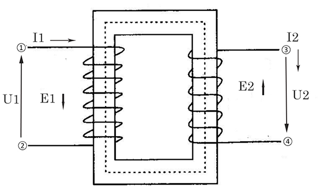
From the picture, we can see that U1 is positively selected AC voltage. When it is loaded on both sides of the primary coil, I1 alternating current and alternating magnetic flux will be generated in the wire. The alternating magnetic flux can pass through the primary coil and the secondary coil along the iron core, thereby achieving a closed magnetic circuit. The mutual induction potential U2 is induced in the secondary coil, and at the same time ① the self-induced potential is also induced in the primary coil, which is E1, which is opposite to the direction of the applied voltage, so it will limit the value of l1. If it is required to maintain the existence of ①, it requires the consumption of the power. In addition, the transformer has the loss. If the secondary current is not connected to the load, but the coil still has the current, it is exactly the no-load current we have mentioned.
Then, if the secondary coil is connected to a load, a current l2 will be generated in the coil, and a magnetic flux ② will be generated at this time, which is opposite to the driving direction of the former ①, and also plays a counteracting role. In addition, the total magnetic flux in the core decreases, the self-inductance voltage E1 also decreases, l1 will increase, so it can be concluded that the primary current and the secondary load are closely related. If the secondary load current increases, l1 will increase, and ① will also increase, then ① the increased part can just be offset by ②, maintaining the total core magnetic quantity unchanged.
The control transformer should go up slowly during use. At the same time, the control transformer is prohibited from moving during operation. It should be noted that the structure of the control transformer limits its ability to work for a long time, and it can only support the work for a short time. If the control transformer is operated for a long time, the transformer will burn out because of the excessive heat generated.
The control transformer can also be used in the chemical industry as a rectifier transformer. At this time, it is only required to rewire the adjustment taps of the control transformer, cut off all power to the equipment, and then adjust the voltage to the control transformer with voltage regulating equipment on both sides, so that it can be used in the chemical industry.
