How does a Soil Moisture Sensor Work?
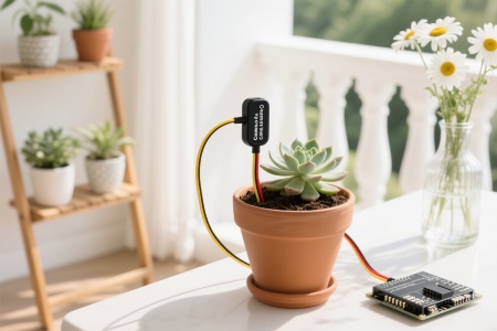
For countless agricultural workers and gardening enthusiasts, determining whether to water the soil has long been a guessing game based on experience. Traditional methods of measuring soil moisture include bending down and inserting a finger into the soil to feel for moisture; observing the color of the topsoil, or weighing a flower pot. However, this guesswork-based irrigation method can easily lead to two outcomes: Overwatering, a massive waste of precious water resources, and potentially causing root hypoxia and nutrient loss; or underwatering, silently causing plant water stress, ultimately impacting their health, yield, and quality. So, how can we overcome these limitations of experience and accurately and scientifically understand the secrets of moisture deep within the soil, truly ensuring "water on demand"? The answer lies in the fruit of modern agricultural technology: Soil moisture sensors.
This article will delve into how soil moisture sensors work, from the science behind them to the different technology types on the market (such as resistive and FDR frequency domain reflectometry). It will also explain how they have made their way from the laboratory to vast farmlands, smart greenhouses, and home gardens, ultimately ushering in a new era of precision irrigation.
Different Types of Soil Moisture Sensors Work Differently
A soil moisture sensor monitors soil moisture. Its hardware control circuit is embedded within the root zone of the crop. The sensor system's detection circuit transmits "excessively high" and "excessively low" humidity signals via an encoder to the main intelligent controller, which then determines the control state. If "excessively high humidity" occurs, irrigation is stopped; if "excessively low humidity" occurs, optoelectronic isolation and relays are used to control a solenoid valve connected to the water source. The system also provides fault alarms. The main intelligent controller communicates with a host computer via a communication interface, enabling real-time monitoring of system operation and data analysis. Soil moisture sensors employ various measurement principles. A common one is based on frequency domain reflectometry (FDR), which measures the propagation characteristics of electromagnetic waves in the soil to infer soil moisture content. Other soil moisture sensors utilize resistance measurement, measuring soil moisture using changes in electrical conductivity as soil moisture levels change.
Resistive/Conductive Sensors Working Principle
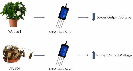
Resistive or conductive soil moisture sensors are based on a simple concept: The conductivity of water. Dry soil is a good insulator, but water dissolves salts to form electrolytes, making the soil conductive. The sensor indirectly determines moisture by measuring the resistance or conductivity between two electrodes embedded in the soil. The lower the resistance (the higher the conductivity), the wetter the soil.
This type of sensor is extremely simple and very low-cost. However, it is susceptible to salt. Fertilizer or other salts in the soil can increase conductivity, resulting in an inflated reading (appearing wetter than it actually is). Passing current can cause electrolytic corrosion of the electrodes, resulting in a shorter lifespan and drift in readings over time. Due to its low price, it is more suitable for hobbyists or short-term projects where accuracy is not a priority.
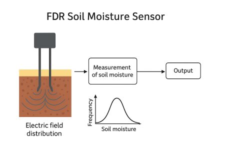
Frequency Domain Reflectometry (FDR) and Capacitive Sensors Working Principle
This type of sensor probe typically consists of a pair of metal electrodes (or probes) buried in the soil, acting like a small capacitor. The soil, along with the water, air, and solid particles within it, acts as the capacitor's dielectric. The sensor applies a fixed-frequency electromagnetic signal (typically in the radio frequency range of tens to hundreds of MHz) to the probe. Water has a high dielectric constant (approximately 80), while soil minerals have a dielectric constant of approximately 3 to 5, and air has a dielectric constant of approximately 1. Changes in soil moisture significantly alter the overall dielectric constant. The FDR sensor measures changes in the probe's impedance or oscillation frequency. Since the probe acts like a capacitor, changes in the soil's dielectric constant affect its capacitance, thereby altering the circuit's resonant frequency or amplitude. Through experimental calibration, a correlation is established between the dielectric constant and the soil's volumetric water content (VWC), ultimately outputting soil moisture data.
This soil moisture sensor offers high accuracy, excellent stability, and more reliable measurements. It is not even slightly affected by salt. Modern FDR soil moisture sensors employ high-frequency measurement techniques to reduce salt interference significantly. They are also highly durable, with no direct current flowing through the probe, preventing electrolytic corrosion and ensuring a long lifespan. Frequency domain reflectometry is currently the most mainstream and cost-effective technology in agriculture, scientific research, and commercial applications. Capacitive soil moisture sensors, as they are commonly known, also fall under the FDR umbrella.
Time Domain Reflectometry (TDR) Working Principle
Time Domain Reflectometry works by transmitting a high-frequency electromagnetic pulse and measuring the time it takes to propagate through and reflect from a probe. The more water present, the higher the dielectric constant, the slower the pulse propagation speed, and the longer the time.
It offers the highest accuracy and is considered the "gold standard" for measuring soil moisture. It is often used in scientific research and to calibrate other sensors. The equipment is complex and extremely expensive. The analog soil moisture sensor sold in the ATO online store uses time domain reflectometry (TDR) technology to measure soil moisture. This sensor offers high measurement accuracy, is minimally affected by soil salinity, and is compatible with a wide range of soil types, making it the best choice for precise soil moisture monitoring!
Comparison Table for Different Soil Moisture Sensors
| Feature Type | Working Principle | Advantage | Disadvantage | Typical Application |
| Resistive type | measures soil resistivity | Affordable and easy to use. | Susceptible to salt/fertilizer, prone to corrosion, and low accuracy. | Suitable for short-term experiments, teaching, and hobbies. |
| Capacitive type | measures soil dielectric constant. | Corrosion-resistant, stable, and cost-effective. | Moderate accuracy, still affected by certain soil properties. | Suitable for home gardening and small potted plants. |
| FDR (Frequency Domain Reflectometry) | measures electromagnetic wave frequency/phase changes | High accuracy, good stability, and minimal salt effects. | High price, may require calibration. | Agricultural irrigation, environmental monitoring, and scientific research |
| TDR (Time Domain Reflectometry) | measures electromagnetic wave reflection time. | High accuracy and strong anti-interference capabilities. | Expensive. | Suitable for scientific research and experiments requiring high-precision measurements. |
How to Calibrate a Soil Moisture Sensor?
Soil moisture sensors indirectly reflect soil volumetric moisture content by measuring changes in dielectric constant, resistivity, or capacitance. Because factors such as soil type (sand, loam, clay), salinity, temperature, and instrument aging can affect measurement accuracy, regular calibration is required to establish an accurate correlation between the electrical signal and moisture content.
Core Calibration Steps
1. Static Calibration Method (Laboratory)
First, perform a saturation point test. Completely immerse the sensor probe in water for a period of time and record the maximum reading as the theoretical saturation value. Next, perform a gradient test. Standard soil samples of varying moisture levels are placed in a dedicated calibration container, and the sensor probe is slowly inserted. Once the reading stabilizes, record the data. Repeat the measurement multiple times at each moisture point and take the average. Finally, perform a drying curve test. By gradually decreasing the moisture content of the soil sample from high to low humidity, this reverses the process to verify sensor response consistency.
2. Dynamic Comparison Method (Field)
First, parallel sampling is performed: Sensors and soil drills are simultaneously embedded in the target plot, collecting soil samples at the same location. Next, a drying and weighing method is used for comparison. The collected soil samples are immediately weighed and then dried in an oven at a specified temperature to a constant weight. The actual mass moisture content is calculated. Finally, data fitting is performed, combining the real-time sensor data with the drying method results through linear or polynomial regression analysis to generate a calibration equation.
Key Correction Factors
Temperature Compensation: Most sensors require the current soil temperature as input. Because low temperatures can cause the dielectric constant to be artificially high, this requires automatic correction via a built-in NTC thermistor.
Salt Correction: Highly saline soils can significantly distort measurement results. A dual-probe design can be used to measure conductivity and dielectric constant separately, removing the effects of salt through a matrix algorithm.
Texture Matching: For coarse soils with a high sand content, a high-frequency measurement mode is recommended. For clay soils, a lower frequency is recommended to improve penetration.
Soil moisture sensors, from the macro to the micro level, have revolutionized water management. Whether managing a farm spanning thousands of hectares or a small flowerpot on a windowsill, they provide scientific, intelligent, and efficient irrigation solutions. If you're looking for the right soil moisture sensor for your needs, ATO industrial online shop sells a wide variety of models for you to choose from!
