How to Achieve Multi-Speed BLDC Control via RS485
In this blog, we'll guide you step by step on how to build and configure a BLDC motor control circuit for multi-speed and direction control using RS485 communication and two self-holding buttons.
Components Overview
Here's what you'll need for this setup:
- BLDC Motor
- Compatible BLDC Motor Controller
- Switching power supply
- USB to RS485 converter
- Two latching buttons
- PC with BLDC control software
- Necessary wiring cables and tools
Circuit Principle
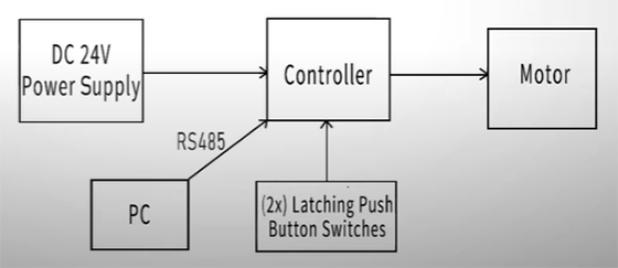
The basic control principle is shown as follows.
- RS485 enables multi-speed settings and directional control.
- And the self-latching buttons provide physical inputs for motor enable and segment speed switching.
- The controller will run the motor at preconfigured segment speeds based on the control logic.
System Wiring and Setup
Wiring Instructions
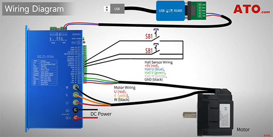
Let's delve into the details of building this circuit.
- Start by connecting the controller to the DC power supply.
- Then wire the BLDC motor to the U, V, and W terminals on the controller, ensuring proper Hall sensor connections if applicable.
- As to latching button connection, wire them to the controller's digital input terminals, with SB1 to X1 for Enable and SB2 to X2 for F/R direction. Both buttons return to COM.
- Connect the RS485 converter to the controller's A (+) and B (-) ports, and plug the USB end into your PC.
- Make sure all wires match the wiring diagram exactly.
Controller Configuration
Before proceeding:
- Turn RV terminal OFF to disable the potentiometer input.
- Set DIP switches SW1 and SW2 to OFF by toggling them up.
This ensures software-based speed control via RS485, instead of manual adjustments.
Physical Wiring Setup
Now for the live setup:
- Connect the USB to RS485 converter to the controller's communication ports.
- Connect SB1 and SB2 to X1 and X2 for Enable and Direction control.
Speed Programming and Startup
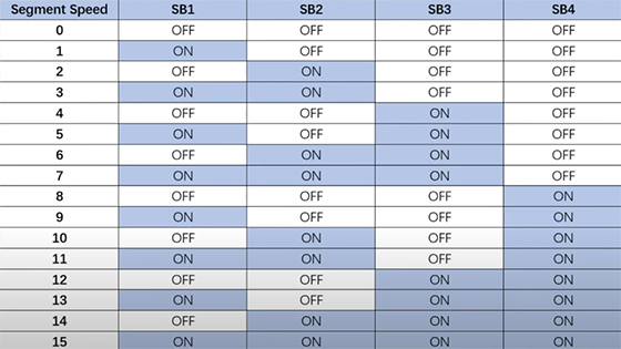
Segment Speed
Here's a table summarizing the ON/OFF combinations of button switches and the corresponding speeds.
Ready for Operation
Power on the system and plug the converter into the PC.
Software Configuration
Launch the BLDC general control software on your PC.
Go to COM setting and click "Connect" to establish communication.
- If successful:
You'll see "COM connect success" and parameters load.
Once complete, it will display "Parameters read to file success"—the setup is complete! - If connection fails:
Verify the COM port in Device Manager and confirm the controller's address (default: 01).
Parameter Settings
If successful, proceed with Parameter Settings.
- Set the following parameters in the software:
- For PN14 (Data Channel), set value to 6 to enable segment speed input as data source.
- For PN15 (Control Channel), set it to 4 to appoint segment speed input as control source.
- Boot up segment speed control by configuring both PN30 and PN31 to 4, assigning X1 to "Enable" and X2 to "F/R".
- Next, set PN16 (Control Mode) to 2 for closed-loop speed control.
Note: In multi-speed control, the max speed is set in PN68.
- Your segment speeds are configured in PN74 to PN89.
- Input desired speed values and apply for each segment.
- The speed range per segment is -32768 to 32767 rpm.
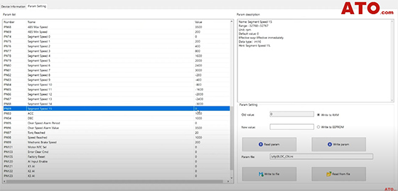
Positive values run the motor in forward, while negative values reverse the direction. And speed zero stops the motor.
Using the software, we'll pre-set segment speeds—enabling clean control of the motor's rotation based on just two tactile buttons.
Operation Demo
Now, let's see the system in action.
- Press SB1 (ON) only.
The motor runs at Segment Speed 1 (e.g., 200 rpm).
If rotation is opposite, reverse the speed sign in the software. - Release SB1 (OFF) and press SB2 (ON).
The motor runs at Segment Speed 2 (e.g., 1500 rpm). - Press SB1 (ON) while SB2 is still ON.
With both switches ON, the motor now runs at Segment Speed 3 (e.g., 3000 rpm). - Release both SB1 (OFF) and SB2 (OFF).
The motor stops.
And there you have it—a fully functional BLDC motor multi-speed and direction control circuit with RS485 and latching buttons!
This setup is ideal for industrial automation scenarios where reliable motor control is critical. If you have any questions, you can watch the video below. For more guides and troubleshooting tips, visit ATO.com.
