How to Control BLDC Motor Speed via PWM Duty Cycle?
In the first part of our tutorial on PWM-based BLDC motor control series, we walked you through how to design a hybrid BLDC motor controller with RS-485, I/O and PWM frequency.
Today, in the second episode, we'll take the next critical step: configuring key parameters to achieve precision speed control via PWM duty cycle. For those just joining us, we recommend reading Part One first. Now, let's dive into duty cycle control!
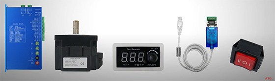
Components Overview
To build this setup, you will need the following components from ATO automation store:
- BLDC Motor and Controller
- USB to RS485 Converter
- PWM Signal Generator
- Rocker Switch (for I/O control)
- DC Switching Power Supply
- PC
Control Principle
The basic control principle of the circuit is described as follows:
The BLDC motor's speed is controlled using a PWM signal from an external generator, while the rotation direction and Enable function are managed via I/O switching using a rocker switch.
All communication and advanced configuration are handled through RS485 protocol, using a USB-to-RS485 converter and a PC running the dedicated BLDC control software.
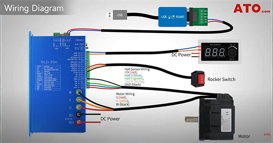
Hardware Installation and Power-up
Wiring Instructions
1. DC Power Supply: Connect the DC 24V power supply to the BLDC controller's power input terminals.
2. Motor Wiring: Wire the motor's U, V, W three-phase leads to the controller.
If your motor has a built-in Hall sensor, connect the Hall wires to the designated terminals on the controller.
3. I/O Rocker Switch: Connect the rocker switch to the controller's X1, X2, and COM terminals.
4. PWM Signal Generator: Power the generator with the DC supply (V+ and V−)
- Connect PWM+ to the controller's PWM input port (PWM 21)
- Connect PWM− to the controller's GND terminal (GND 22)
This controls motor speed via PWM frequency input.
5. RS485 Communication
- Connect the T/R+ and T/R− ports of the USB to RS485 converter to the A and B terminals on the controller.
- Plug the USB side into your PC.
This enables software control over speed and parameters.
Controller Configuration
Before powering up:
- Disable manual speed control by using a screwdriver to rotate the built-in RV Potentiometer fully CCW;
- Configure DIP switches: Set SW1 and SW2 both to OFF to enable external PWM and I/O logic control.
Physical Wiring Setup
- USB-RS485 Converter connects to the motor controller's RS485 interface.
- PWM Signal Generator links to the controller's PWM port and GND.
- Rocker switch connects to X1, X2 and COM for motor Enable and F/R control.
Refer to the video segment after 2:35 for detailed explanation of Rocker switch motor control principles: 'IO + SV' Control of BLDC Motor.
Ready for Operation
Plug the RS485 converter into your PC's USB port and power up the system.
Software Setup
Now let's configure the parameters for our desired control method.
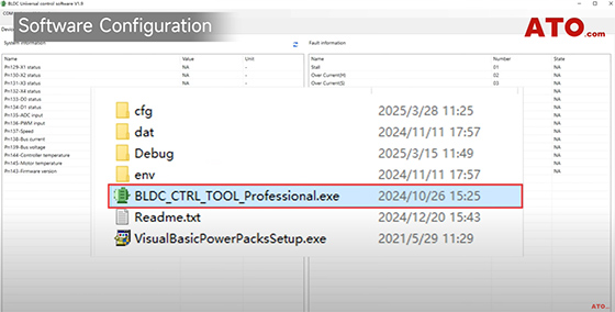
Unlike the PWM frequency control method we demonstrated earlier, we now need to set PN14 (Data Channel) to '4'—this selects PWM duty cycle as the primary speed command input.
- Set PN15 (Control Channel) to 1 to select I/O Switching as command source.
- Set PN30 (X1 Function) to 0 to designate X1 as motor Enable control.
- Set PN31 (X2 Function) to 1 to assign F/R direction toggle to X2.
For parameters PN32 (X3 Function) and PN33 (X4 Function), you can enable and configure additional features according to the parameter table. For example:
- Set PN32 to 2 to enable brake control functionality.
- Set PN33 to 3 to configure error clear/reset control.
Important note on parameter activation: Parameters PN14 and PN15 require a system reboot to take effect, while PN30 to PN33 are immediately active upon adjustment.
Operation Demo
Let's begin our hands-on demonstration.
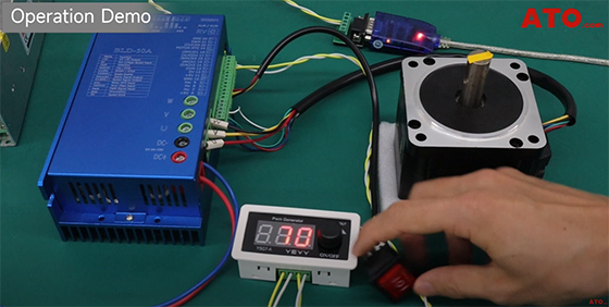
1. Starting and Forward Operation
- Flip the rocker switch to "I" to enable the motor.
- Tap on the knob to initiate PWM pulse output.
The motor begins rotating in the clockwise direction at our initial 70% duty cycle setting.
2. Speed Control
Rotate the PWM generator's knob to adjust the duty cycle and thereby control the motor speed.
Important notes:
- This BLDC controller accepts PWM duty cycles from 0 to 100% at frequencies between 100Hz and 1000Hz.
- When the duty cycle reaches 100%, the motor runs at the maximum speed specified earlier in PN02, which in this case is 3000 rpm.
3. Real-time Monitoring
You can monitor the following parameters in real time in the "System Information" tab of the PC software:
- PN136: Current PWM input signal duty cycle
- PN137: Real-time motor speed
4. Stop and Reverse Operation
- Switching the rocker switch to 0 stops the motor.
- Flip the switch to position II. The motor reverses instantly.
And PWM still controls the reverse speed via duty cycle adjustments.
This proves full speed and directional control using RS485, PWM duty cycle, and I/O switching. If you want to know more details, please click the video below.
