How to Wire and Control a Single-Phase Dual Capacitor Motor?
Single-phase motors are widely applied in household appliances, workshop equipment, and light industrial machinery because of their straightforward design and dependable performance. Among these, the dual capacitor motor stands out as one of the most commonly used. This guide will explain its wiring procedure, operating principle, and methods for forward and reverse control.
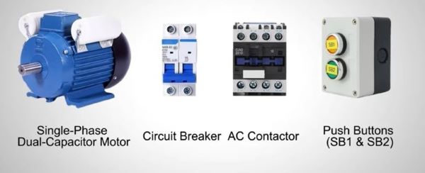
Required Components
To build the control circuit, the following components are needed:
These components form the core of our demonstration, where the circuit breaker ensures protection, the contactor controls the motor operation, and push buttons are used for start/stop actions.
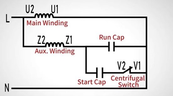
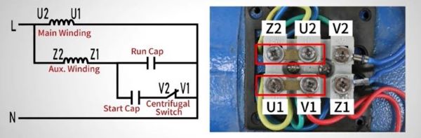
Internal Schematic
The internal structure of a dual capacitor motor consists of a main winding and an auxiliary winding, connected in parallel. Power is supplied by the live wire (L) and neutral wire (N).
Two capacitors are integrated into the motor:
- Starting Capacitor – provides extra torque during startup.
- Running Capacitor – maintains high efficiency and stable performance during continuous operation.
A centrifugal switch is mounted on the motor shaft. Its operation is automatic:
- At low speed (startup stage), the switch remains closed, keeping the starting capacitor in the circuit to supply additional torque.
- Once the motor reaches rated speed, the switch opens, disconnecting the starting capacitor, leaving only the running capacitor active.
Motor Reversal Principle
Reversing the rotation direction is straightforward. It only requires swapping the terminal connections U1 and U2.
This action changes the phase relationship between the windings, thereby reversing the magnetic field direction and the motor’s rotation.
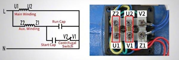
Wiring Demonstration
The motor has six terminals along with two copper connectors. By changing the connector placement, we can achieve clockwise (CW) or counterclockwise (CCW) rotation.
Counterclockwise Rotation (CCW)
- Connect Z2 to U1 and U2 to V1 (vertical connection).
- Press SB2 → the contactor engages → the motor runs CCW.
- Press SB1 → the motor stops.
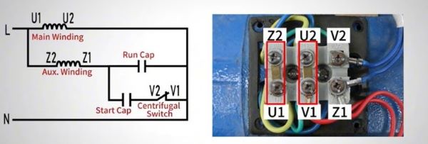
Clockwise Rotation (CW)
- Connect Z2 to U2 and U1 to V1 (horizontal connection).
- Press SB2 → the contactor engages → the motor runs CW.
- Press SB1 → the motor stops.
This wiring method provides a simple yet effective way to control motor direction.
Conclusion
Our demonstration on how to wire and control a single-phase dual-capacitor motor comes to an end here. By taking advantage of this technology, you can control the start, operation, and reverse rotation of single-phase motors. If you have any questions, you can watch the video below.
