How to Wire DC Contactor for Electric Tricycle?
The Importance and Basic Principles of DC Contactor Wiring
In modern electric tricycles, the DC contactor, as a crucial circuit component, plays an indispensable role. It not only controls the start and stop of the motor but also plays a key role in switching the battery current. Improper DC contactor wiring can not only affect the performance of the electric tricycle but can also cause battery damage, control system failures, and even threaten driving safety in serious cases. Therefore, ATO Automation will provide essential and correct wiring methods for every electric tricycle user and maintenance technician.
Basic Principles of DC Contactors
A DC contactor is a device that controls the on/off state of a circuit through electromagnetic induction. When an electric tricycle starts, the contactor closes the circuit, allowing current to flow from the battery to the motor. When braking or stopping, the contactor breaks the current and stops the motor from running. Its core operating principle involves generating a magnetic field through an electromagnetic coil to attract the DC contactor's contacts, thereby controlling the flow of current.
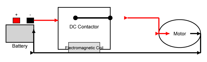
Fig 1: DC contactor - circuit closed
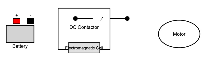
Fig 2: DC contactor - circuit open
Electric tricycles typically use brushless DC motors, which require precise current control through a DC contactor. In the design of a contactor, key components include main contacts, auxiliary contacts, and an electromagnetic coil. The main contacts are responsible for carrying the current, while the auxiliary contacts are used for other control functions.
The Function of DC Contactors Wiring in Electric Tricycles
The correctness of contactor wiring directly affects the performance and safety of electric tricycles. The primary function of a contactor is to control the flow of current. Through wiring, users can control the start/stop status of the electric tricycle, the charging and discharging process of the battery, and the power output of the motor according to their needs.
For electric tricycles, the DC contactor is not merely a simple switching device; it also performs multiple functions such as battery management, energy-saving control, and motor protection. Incorrect wiring may lead to serious issues such as the motor failing to start, battery damage, or even fires. Therefore, proper contactor wiring is the primary condition for ensuring the safe and reliable operation of electric tricycles.
Common Issues with DC Contactor Wiring
During the use of electric tricycles, many users and maintenance personnel encounter issues during wiring, primarily including the following:
- Wiring Errors: When replacing or repairing a contactor, improper wiring may prevent the motor from starting normally or cause excessive battery discharge.
- Contactor damage: If the contactor's contacts are faulty or the electromagnetic coil is damaged, it may cause the electric tricycle to run unsteadily.
- Current overload: Due to the contactor's capacity limitations, if the current exceeds its load range during wiring, it may cause the contactor to burn out or even trigger an electrical fire.
To avoid these issues, we need to have a clear understanding of the DC contactor wiring process, know the correct wiring methods, and avoid common mistakes. ATO will provide a detailed introduction to the wiring steps and precautions for DC contactors.
DC Contactor Wiring Steps and Precautions
Preparations
Before wiring the DC contactor for an electric tricycle, you must first prepare the necessary tools and materials. Common tools include screwdrivers, electrical tape, wire cutters, etc. The contactor model must match the battery voltage and motor power of the electric tricycle to ensure that its rated current is not lower than the normal current load of the electric tricycle.
After completing the preparatory work, turn off the power and ensure that the electric tricycle's battery is disconnected to prevent short circuits or electric shock accidents during the wiring process.
Verify the DC contactor's terminal connections
DC contactors typically have three main terminal connections: Battery positive terminal, battery negative terminal, and motor terminal. The contactor's terminal connections are usually clearly labeled to ensure that each terminal's electrical function is correct.
- Battery positive terminal (B+): This terminal connects to the battery's positive terminal for the power supply.
- Battery negative terminal (B-): This terminal connects to the battery's negative terminal to complete the current circuit.
- Motor terminals (M+/M-): These terminals connect to the motor, controlling the direction of current flow to the motor via the contactor to control the motor's start/stop operation.
There are also auxiliary contact terminals used for additional control circuits, such as battery charge monitoring and motor speed regulation.
Wiring Steps
Step 1: Connect the positive terminal (B+) of the battery to the positive terminal of the contactor, ensuring the connection is secure and tight.
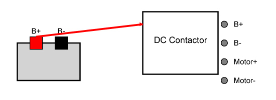
Fig 3: Step 1 - Battery positive connection
Step 2: Connect the battery's negative terminal (B-) to the contactor's battery negative terminal.
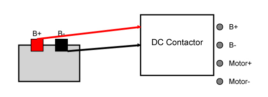
Fig 4: Step 2 - Battery negative connection
Step 3: Connect the motor's cable to the contactor's motor terminals, ensuring proper wiring according to the motor's polarity.
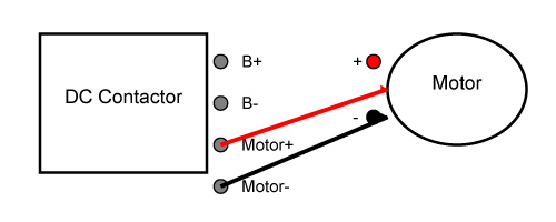
Fig 5: Step 3 - Motor cable connection
Step 4: Inspect all connection points to ensure secure wiring, no short circuits, and no exposed wires.
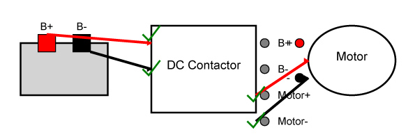
Fig 6: Step 4 - Connection inspection
Safety Precautions
During the wiring process, in addition to ensuring that the cables are connected correctly, the following safety precautions must also be observed:
- Avoid wiring errors: Before wiring, carefully check the battery voltage and motor power to ensure that the contactor's rated values meet the requirements.
- Avoid overloading: Never exceed the contactor's load capacity; overloading can cause the contactor to malfunction.
- Prevent short circuits: During wiring, avoid cable contact with metal parts to prevent short circuits.
- Check contactor status: After completing the wiring, inspect the contactor's operational status to ensure it functions normally.
Regular Inspection and Maintenance
Once the wiring is complete, it does not mean that maintenance of the contactor can be neglected. Regularly inspect the condition of the contactor, clean the contact points, prevent dust accumulation and oxidation, and maintain good electrical conductivity. Regularly check whether the connections between the battery and motor are secure to prevent faults caused by loose wiring.
Through the above wiring steps and precautions provided by ATO Automation, you should now have a comprehensive understanding of the wiring for the DC contactor in an electric tricycle. Mastering these techniques will not only ensure the normal operation of the electric tricycle but also extend the lifespan of the battery and motor, enhancing driving safety and comfort.
