How to Build a 2-axis Robotic Arm with PLC & HMI?
In industrial automation applications, pick-and-place is one of the most common and fundamental motion control scenarios. Many users perceive robotic arm systems as complex and high-cost, but in reality, a structured, logically complete 2-axis robotic arm control system can be quickly built using PLCs, HMIs, and stepper motors. Taking a simulated 2-axis robotic arm project controlled by a PLC + HMI with dual stepper motors as an example, this article will detail the system architecture, wiring methods, driver configurations, PLC & HMI programming concepts, as well as the full operation and emergency stop logic. It aims to help you quickly understand and get started with similar applications.
I. Why Choose PLC+HMI Solution?
Compared to pure microcontroller control, the PLC+HMI combination offers inherent industrial advantages. PLCs boast strong anti-interference capabilities and can stably output pulses to control motors. HMIs provide an intuitive operation interface, allowing parameter adjustments and action triggering without modifying code. This cost-effective solution can be directly migrated to real-world production scenarios, such as small assembly lines and material sorting equipment, making it highly practical.
II. Components
To get started, you'll need a few key components:
- PLC: The brain of your system, responsible for executing logic and sending pulse signals to control the motors.
- HMI: Used to control parameters and trigger motion sequences.
- Stepper Motors×2: These motors, attached to linear slides, control the X and Y axes' movement.
- Stepper Drivers×2: These devices receive commands from the PLC and translate them into motor movements.
- 24V DC Power Supply (ATO Switching Power Supply): Powers the entire system.
III. Control Principle
The system is simple yet effective. Here’s how it works:
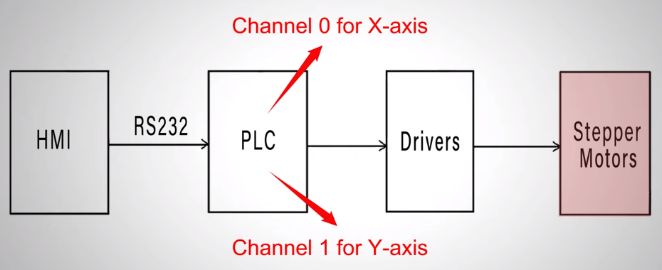
- Commands are given through the HMI.
- The HMI sends these commands to the PLC via RS232.
- The PLC outputs pulse signals to the stepper motor drivers.
- Each motor’s driver (one for the X-axis and one for the Y-axis) independently controls its respective motor’s movement.
IV. Full Process from Wiring to Debugging
1. Physical Setup
The physical setup involves wiring and connections:
- The PLC and HMI are linked by an RS232 cable.
- Pulse output channels from the PLC connect to the respective motor drivers.
- Stepper motors are wired to the drivers, with each driver output corresponding to its motor.
Wiring Schematic
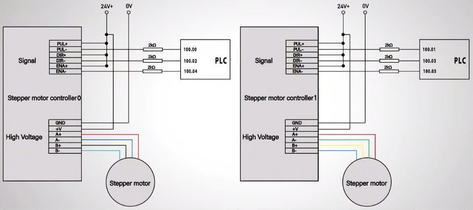
Refer to the wiring schematic to ensure all components are correctly connected:
- The RS232 cable links the PLC to the HMI.
- The motor drivers connect to the motors through the A+, A-, B+, and B- terminals.
- Pulse outputs from the PLC link to the PUL+ and DIR+ terminals on the drivers.
2. Driver DIP Switch Settings
Configure the DIP switches on your motor drivers:
- Set the Peak Current and RMS Current according to your motor’s specifications.
- Adjust the pulse-per-revolution ratio. For optimal performance, we’ve configured the system to 1000 pulses per revolution.
3. PLC Programming
(1) Communication Configuration
First, set the communication parameters between the PLC and HMI in the software: Ensure the PLC model, COM port, and baud rate fully match the HMI. Otherwise, command transmission will fail. For detailed configuration guidance, refer to the dedicated communication setup video on the ATO channel.
(2) Position Control Logic
This is the core for realizing "move to target position → return to origin":
- Upon receiving the start signal (W0.04), both the X-axis (pulse count stored in D0) and Y-axis (pulse count stored in D10) output pulses clockwise at 1000Hz simultaneously.
- Use the PULS instruction to define the total number of pulses (controlling movement distance) and the SPED instruction to set the pulse output mode, direction, and frequency.
- After reaching the target position, the motors stop automatically and wait for the "Action Complete" signal (W0.06).
- When the "Action Complete" signal is triggered, the X/Y axes rotate counterclockwise with the same number of pulses to return to their initial positions.
(3) Emergency Stop & Resume Logic
Safety first! The emergency stop function must be reliable:
- Pressing the emergency stop button (W0.05) immediately stops pulse output for both axes, and the motors halt instantly.
- The system automatically records the number of pulses sent (X-axis stored in D2, Y-axis stored in D12) for calculating the remaining travel later.
- After resetting the emergency stop, the operator can choose to "continue to target position" (output remaining pulses) or "return to origin" (output the sent pulses in the reverse direction).
(4) Data Reset Logic
After reaching either the target position or origin, the pulse output completion flag triggers a data reset, clearing registers such as D2, D12, D4, and D14 to ensure accurate pulse counting for the next cycle.
4. HMI Programming
The HMI interface is set to map commands to specific PLC registers:
- The X-axis total pulses map to register D0.
- The Y-axis total pulses map to register D10.
- Additional controls like start, stop, and emergency stop buttons are linked to the corresponding PLC signals.
V. Test Verification
With everything ready, let’s conduct a live test:
- Enter parameters on the HMI: 15,000 pulses for the X-axis and 20,000 pulses for the Y-axis.
- Click "Start"—both axes start simultaneously and move accurately toward the target position.
- After the preset pulses are completed, the motors stop automatically. Press "Action Complete" to make both axes return to the origin smoothly.
- Start again, then press the emergency stop button during motion—the motors halt instantly. After resetting the emergency stop, select "Continue to Target," and the system automatically calculates the remaining pulses to complete the subsequent travel.
VI. Conclusion
This article provides a complete guide to building a two-axis robotic arm using PLC and HMI for precise stepper motor control. From system design and hardware wiring to driver setup, PLC programming, and real-world testing, each step is explained clearly—making industrial-grade automation accessible even for beginners.
Ready to build your own? Grab all the necessary components from our ATO one-stop online store, and follow along with the detailed video below. Start creating your automated pick‑and‑place system today!
