How to Automate Stepper Motor Direction with PLC & HMI
In many industrial automation scenarios, mechanical components require reciprocating motion, and automatic forward and reverse rotation is the most direct way to achieve this functionality. Combining a PLC, an HMI, and proximity sensors to build an automatic forward and reverse control system for stepper motors allows for complex control and system integration. In this tutorial, we'll show you how to connect and configure a hybrid system using a PLC, an HMI, and proximity sensors to achieve automatic forward and reverse control of a stepper motor.
Device Preparation
To implement automatic forward and reverse control of a stepper motor, you need the following basic components. All of these high-efficiency, high-quality components are available from the ATO online store.
- PLC (Programmable Logic Controller)
- HMI (Human Machine Interface)
- Stepper motor
- Stepper driver
- Two proximity sensors
- a DC power supply
Core Control Principles of the System
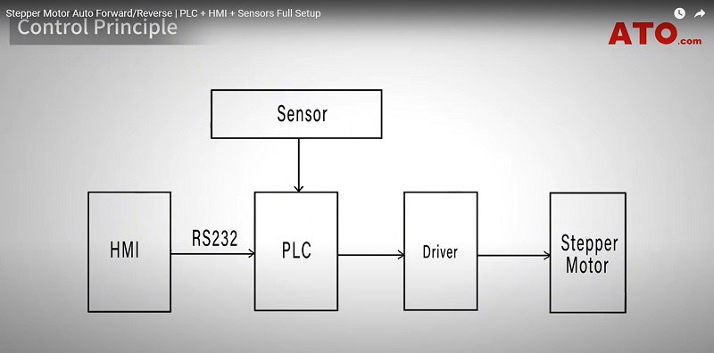
The system's core control principle relies on centralized command and coordination by a programmable logic controller (PLC). Operators set commands and monitor operating status through a human-machine interface (HMI). The HMI and PLC exchange data via an RS232 serial communication interface. As the control hub, the PLC outputs pulse (PUL) and direction (DIR) signals to the stepper motor driver according to its internal program. The driver receives these signals and converts them into precise current and voltage to power the stepper motor, driving it at the desired speed and direction. This ultimately translates into precise linear motion of the actuator (such as the slider).
To ensure safe and reliable system operation, two proximity sensors are installed at the extreme ends of the motion path and connected to the PLC's digital inputs. They monitor the slider's position limits in real time and transmit feedback signals to the PLC. Based on these sensor signals, the PLC program instantly changes the direction signal output to the driver to control the motor's automatic forward and reverse rotation. It also stops pulse output when the limit is reached, effectively preventing overtravel of the actuator and ensuring safe and reliable operation of the entire system.
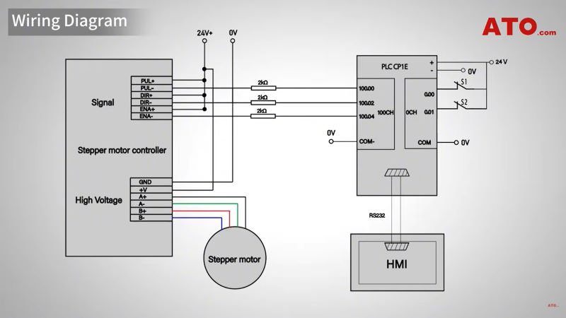
Wiring Diagram
Physical Setup
Before proceeding with the physical wiring, first ensure that the PLC and proximity sensor are properly connected. During the physical wiring setup, ensure that the connections between the PLC and proximity sensor are correct. Regarding the physical wiring of the stepper driver, configure the DIP switches on the driver based on the motor's rated current and the desired microstepping resolution to achieve optimal speed and smoothness. This article demonstrates using a stepper driver set to a common resolution, such as 1600 pulses per revolution, to ensure smooth motion.
PLC Programming
The first step in PLC programming is to open the programming software and establish a communication connection between the PLC and the HMI. Ensure that the communication parameters on both devices, such as brand, model, COM port, and baud rate, are identical. This is the foundation for all subsequent control functions. For detailed configuration instructions for this step, please refer to the "HMI and PLC Programming and Testing" video tutorial on the ATO YouTube channel.
The core logic of the program consists of four main components: Forward start control, reverse start control, motor stop function, and sensor status indication. Because CNC sensors are used, corresponding input conditions must be configured when writing the ladder logic.
When the operator presses the "Forward Start" button on the HMI, the PLC outputs a continuous pulse signal at a frequency of 1500Hz to the driver, causing the motor to rotate clockwise and the slider to move in the forward direction. If the slider hits the forward limit sensor, the motor stops immediately. Simultaneously, a 500ms timer named T000 is triggered. When the timer expires, the system automatically switches to reverse mode. At this point, the PLC begins outputting the same 1500Hz pulse signal, but with the direction signal changed, causing the motor to reverse.
When the slider reaches the reverse limit sensor, the above process repeats: The motor stops, another timer, T001, starts counting, and the motor resumes forward rotation. This cycle repeats, creating a continuous, automatic reciprocating motion of the slider. To stop the system mid-process, simply press the stop button (corresponding to address W0.01) on the HMI.
HMI Programming
The HMI configuration process is relatively simple. The core task is to correctly map the various buttons and indicators on the screen to the corresponding addresses defined in the PLC program. For example, the CW and CCW indicators, used to indicate the motor's direction, need to be associated with PLC addresses W1.00 and W1.01, respectively. The function buttons on the screen, including the forward start button, reverse start button, and stop button, need to be mapped to PLC addresses W0.00, W0.02, and W0.01, respectively. By completing these address associations, the HMI can monitor and operate the PLC system.
Test Run Steps
After completing all settings, you can perform a test run to observe the system in action.
- Press the "Forward" button, and the slider will begin moving to the right.
- When the slider hits the clockwise limit sensor, the corresponding indicator light will illuminate, and the motor will stop. After a brief pause, the system will automatically reverse the motor, and the slider will begin moving to the left.
- If the "Stop" button is pressed during operation, all movement will immediately stop. Press the "Backward" button, and the slider will move to the left until it hits the counterclockwise limit sensor, at which point the indicator light for that direction will illuminate.
- After a brief pause, the slider will automatically return to the right. This cycle continues as long as the system is not manually stopped, providing automatic reciprocating motion for the slider.
Conclusion
You've now successfully built an automatic forward and reverse rotation control system for a stepper motor. This system can enhance automation, enable complex control and system integration, create complex motion trajectories, achieve closed-loop error correction, and provide precise positioning. It also enables the motor to flexibly respond to sensor signals and host computer commands, becoming part of an intelligent system.
If you have any questions, please watch the video below. For more guides and troubleshooting tips, visit ATO.com.
