PLC & HMI Controlled Bidirectional Dual Stepper Motors
In the field of process automation, to build a clearly structured, stable, reliable, powerful, and easy-to-maintain industrial control system, a basic automation project can be employed: using a PLC and an HMI to simultaneously control the forward and reverse motion of two stepper motors via RS232 communication.
- PLC: Responsible for core control logic and real-time pulse transmission.
- HMI: Provides user-friendly and flexible human-machine interaction and data management.
- RS232: The reliable "nerve" connecting the "brain" and "skin" (operator interface).
- Stepper driver: The "nerve ending and amplifier" that receives brain commands and drives muscle (motor) movement.
This combination fully leverages the strengths of each component and is an optimal solution for complex motion control tasks in industrial environments. This article demonstrates how to control dual stepper motors in both forward and reverse directions using PLC and HMI. It covers the setup, programming, and practical implementation, enabling automatic bidirectional motion for industrial applications. The guide is ideal for engineers and technicians looking to streamline stepper motor control with user-friendly HMI interfaces.
System Architecture
First, let's prepare for this project. All the components you need are available from ATO. The following block diagram illustrates the basic architecture.
- A PLC (Programmable Logic Controller)
- An HMI (Human Machine Interface)
- Two Stepper Motors and their corresponding Stepper Motor Drivers
- A 24V DC Switching Power Supply
This is a classic introductory and intermediate industrial automation project. Its core goal is to build an automated system that precisely controls two stepper motors for forward and reverse rotation, speed regulation, and positioning. This system uses a programmable logic controller (PLC) as the control brain, while a human-machine interface (HMI) provides intuitive operation and monitoring, enabling both manual and automatic control of the motors' motion.
The PLC (Programmable Logic Controller) generates high-frequency pulse signals (Pulse) and sends them to the driver. Each pulse corresponds to a microstep of the motor. The PLC generates a direction signal (Direction) whose high and low levels determine the motor's forward or reverse rotation. It also processes safety signals (such as emergency stop and limit switches) and immediately stops pulse output. The stepper motor and driver acts as a bridge between the PLC and the motor. It receives weak electrical pulses and direction signals from the PLC and amplifies them to generate sufficient power to drive the motor. The stepper motor and driver convert the electrical pulses into precise angular displacement. Each pulse causes the motor to rotate a fixed angle, enabling precise open-loop control.
Real-time System Setup
Here's how all the components work. The HMI sends commands to the PLC via RS232 communication. The PLC then executes its program, sending pulse and direction signals to the two stepper drivers, which ultimately drive the motors.
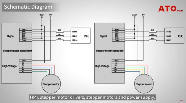
Schematic Diagram
The following wiring diagram shows the connections between the PLC, HMI, stepper motor driver, stepper motor, and power supply.
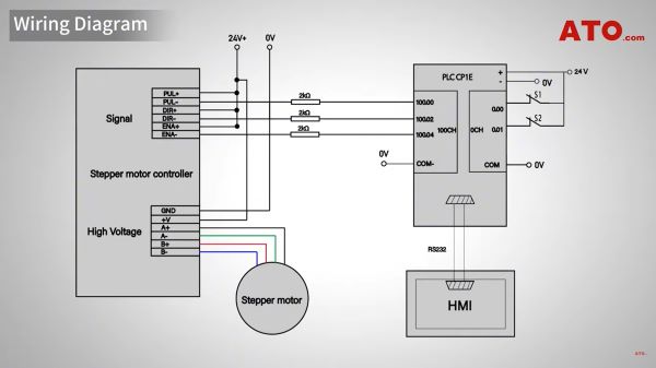
To ensure correct wiring, carefully follow the wiring diagram. Connect the stepper motor driver to the PLC according to the wiring diagram. Start by connecting the yellow cable to pulse output 0 and the white cable to pulse output 1. For more detailed steps, please watch the video tutorial on the ATO YouTube channel.
Driver Setup
Before applying power, we must configure the driver using these DIP switches. The specific settings depend on your motor specifications.
For our demonstration motor, set the peak current and rms current DIP switches to match the motor's rated current, for example, 2.84A and 2.03A. The microstepping resolution is preset to 1000 pulses per revolution (PPR). Be sure to consult your motor and driver datasheets for these values. Once the hardware is ready, let's configure the logic.
PLC Programming
Open the PLC programming software and set up communication between the PLC and HMI. Ensure that the communication parameters (such as brand name, COM port, and baud rate) match exactly between the PLC and HMI. For a detailed tutorial on this setup, watch the video "HMI and PLC Programming and Testing" on our channel.
The PLC program consists of two main logic sections: forward start and stop, and reverse start and stop.
When input W0.00 is triggered, we execute the SPED (Speed Output) instruction. We set it to pulse output 0, continuous mode, and a frequency of 3000 Hz, so the motor rotates clockwise at that speed. Simultaneously, bit Q100.00 is set to ON. When W0.00 is turned on (the HMI button is released), another "SPED" instruction is executed with a frequency of 0 Hz, stopping the motor and resetting Q100.00 to OFF. The reverse logic is the same, but triggered by W0.01. When input W0.01 is closed, the PLC outputs 3000 Hz pulses for counterclockwise rotation.
The same indicator logic applies, using bit Q100.01 to indicate the reverse state. After releasing W0.01, the motor is stopped by setting the frequency to 0 Hz and resetting Q100.01 to OFF. This program logic is suitable for both stepper motors.
HMI Programming
On the HMI interface, we created two momentary buttons: Forward and reverse. We connected the forward button to PLC address W0.00. We connected the reverse button to PLC address W0.01. This allows the operator to easily control the motor with a simple touch of the screen.
System Operation
Now that the configuration is complete, let's see how the system works. Press and hold the "Forward" button. Both motors begin rotating clockwise in sync, moving the slider to the left at the same speed. Press and hold the "Backward" button, and the motors will rotate counterclockwise, moving the slider in the opposite direction. Releasing either button will cause the motors to stop immediately.
For detailed configuration instructions, see the Dual Stepper Motors Forward/Reverse Control with PLC & HMI video tutorial on the ATO YouTube channel.
Conclusion
In summary, this project is more than just a simple motor forward and reverse control. It is a micro-industrial automation system that integrates logic control, human-computer interaction, motion control, and safety design, perfectly demonstrating the essence of modern industrial control. For more technical information, please visit ato.com
