How to Program a PLC for Auto Level Control
In this quick tutorial, you'll learn how to create a simple yet FAIL-SAFE PLC program for water level control with tuning fork sensors and solenoid valves. Let's get started!
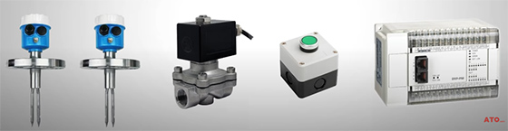
Setup Components
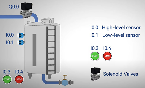
System Overview
We are building an automatic water level control system for a tank. Here are the core components and their functions:
Tank & Sensors:
- A water tank with two tuning fork level sensors monitor the water level.
- High-Level Sensor: Connected to PLC input I0.0.
- Low-Level Sensor: Connected to PLC input I0.1.
Control Goal: Maintain the water level between the two level sensors.
User Control:
- Start Button: Connected to input I0.3.
- Stop Button: Connected to input I0.4.
Actuator: An inlet solenoid valve is connected to output Q0.0 for water supply.
The system automatically refills the tank when the water falls below the low-level sensor and stops filling when it reaches the high-level sensor.
Basics of Tuning Fork Level Sensors
Before we dive into the program, let's quickly understand the tuning fork level sensors.
Tuning fork level switches are vibration-based sensors. A piezoelectric crystal causes the fork to vibrate at a specific frequency. When the sensor's prongs are in air, they vibrate freely at their natural frequency.
However, when submerged in liquid—like water—the frequency drops. This frequency shift triggers an internal relay, giving you a discrete switch output signal, perfect for PLC inputs. This makes tuning fork sensors highly accurate and resistant to foam, turbulence, or material buildup.
More importantly, they provide instant response that's faster than float switches. That's why we used tuning fork sensors for our project.
PLC logic step-by-step
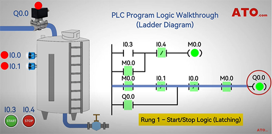
Now, let's walk through the PLC logic step-by-step using a simple ladder diagram.
Here, we've integrated two level switches to I0.0 (NC for High Level) and I0.1 (NC for Low Level), and Start button's NO contact to I0.3, the Stop button's NC contact to I0.4.
Rung 1 – Start/Stop Logic (Latching)
When you press the Start button, internal relay M0.0 latches ON.
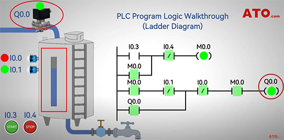
Rung 2 – Solenoid Valve Control
The solenoid valve (Q0.0) opens, allowing water into the tank.
Bypassing Low Level: As water rises past the low-level sensor, its NC contact (I0.1) opens. The valve remains energized via the self-holding contact.
High Level Reached: When water triggers the high-level sensor (I0.0), the valve (Q0.0) de-energizes, stopping the water inflow.
Water Consumption: The high-level sensor resets (I0.0 closes) as the level drops. The valve remains off while the low-level sensor (I0.1) is still submerged (contact open).
Refill Triggered: Once the level falls below the low-level sensor, I0.1 activates (contact closes), re-energizing the valve (Q0.0) to restart the fill cycle.
Stop Logic
Pressing the Stop button (I0.4) unlatches M0.0, stopping the automatic refill process. And that concludes our demonstration of a simple PLC liquid level control program.
If you have any questions about the components, you can watch the video below. For more PLC guides and to explore the hardware, visit the ATO one-stop online store.
