How to Make a Variable DC Power Supply?
A variable DC power supply is a practical device that can adjust its output voltage based on demand. It's widely used in electronics experiments, lighting control, and regulating electric heating equipment. This article describes a simple method for making a 0-220V adjustable DC power supply, suitable for applications such as adjusting the brightness of an incandescent bulb or the temperature of a soldering iron.
- Principles of Variable DC Power
- Materials for Building a Variable Supply
- Step-by-Step Construction Guide
- Operating Your Variable Supply Safely
Principles of Variable DC Power
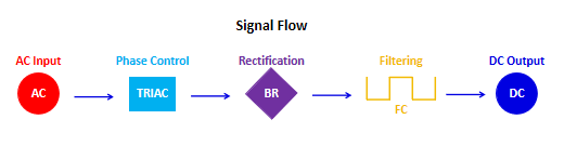
The basic principle of creating a variable DC power supply is based on AC voltage regulation and rectification technology. 220V AC power is first phase-regulated by a bidirectional thyristor (TRIAC). Adjusting the potentiometer changes the conduction angle of the trigger diode, thereby controlling the effective value of the output voltage. The regulated AC power is then converted to DC by a rectifier bridge and filtered by a capacitor to produce a smooth DC output. The entire process can be accomplished with a small number of components, with potentiometer adjustment being the key control step in creating an adjustable DC power supply.
Materials for Building a Variable Supply
The materials needed to create a variable DC power supply include seven core components:
- A 500K potentiometer
- A DB3 bidirectional trigger diode
- A BT136 triac
- A 39K current-limiting resistor
- A 275V safety capacitor of 0.1μF
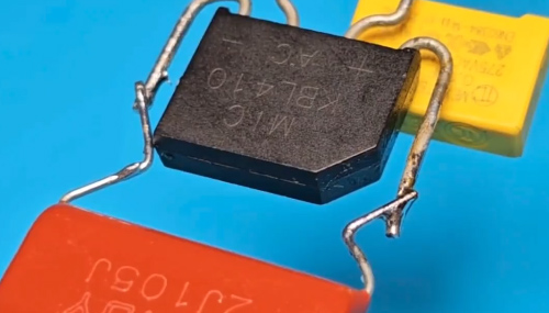
- A 1000V bridge rectifier with a current of 4A or more
- A 400V CBB capacitor with a capacity of 1μF
These components must meet the required specifications, ensuring that their voltage and current ratings are suitable for a 220V input. You can also prepare an incandescent bulb and a multimeter to test the output voltage.
Step-by-Step Construction Guide
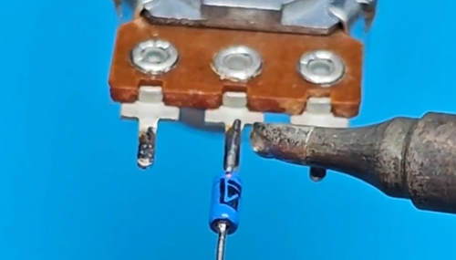
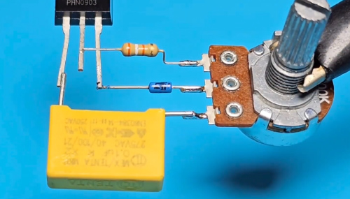
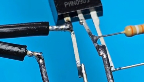
Step 1: Connect one end of a DB3 trigger diode to pin 2 of a 500K potentiometer. The bidirectional trigger diode at the wiper end ensures proper triggering of the thyristor.
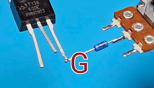
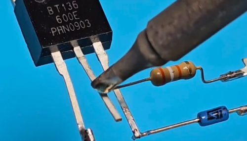
Step 2: Connect the trigger terminal (G) of a BT136 bidirectional thyristor to the other end of the DB3 trigger diode.
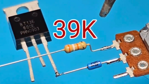
Step 3: Connect a 39K resistor in series with pin 1 of the 500K potentiometer to prevent the potentiometer from zeroing.
Step 4: Connect one end of a safety capacitor to pin 3 of the 500K potentiometer and the other end to terminal T1 of the BT136 bidirectional thyristor. The safety capacitor provides trigger current for the thyristor.
Step 5: Connect the other end of the 39K resistor to terminal T2 of the bidirectional thyristor.
Step 6: The two middle pins of the rectifier bridge are the AC input terminals; polarity does not need to be distinguished. Connect one of these pins to terminal T2 of the bidirectional thyristor.
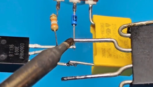
Step 7: Connect a CBB capacitor in parallel to the output terminals of the rectifier bridge, namely pins 1 and 4. After the AC power is rectified by the bridge rectifier, it is filtered by this capacitor to produce a DC power supply.
Step 8: Connect the T1 terminal of the thyristor and the other pin of the AC input terminal of the bridge rectifier to the input power supply.
Step 9: The terminals of the capacitor are the DC output terminals of this circuit. Connect an incandescent bulb to the output terminals to test it. Because the output is DC power, the multimeter should be set to the DC voltage range.
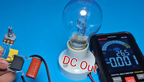
Step 10: Test the output voltage of the variable power supply. After connecting 220V AC power to the input terminals of the circuit, adjust the output voltage using the potentiometer. Observe the light bulb; it should gradually become brighter from dark, indicating that the adjustable DC power supply is working successfully.

Operating Your Variable Supply Safely
To ensure your absolute safety in the process of making a variable DC power supply, ATO automation hereby provides the following important safety regulations. Please be sure to read and comply with them carefully before use.
High Voltage Danger Warning
This circuit is directly connected to 220V and is not isolated. The entire circuit board may be live! Extreme caution must be exercised during construction, debugging, and testing. Do not touch any conductors with your bare hands.
Component Specifications
Be sure to use components with sufficient voltage ratings, especially safety-rated capacitors and CBB capacitors. Otherwise, there is a risk of breakdown and explosion. The current capacity of the rectifier bridge and thyristor should be greater than the current required by your load.
Soldering and Layout
Ensure secure soldering to avoid cold solder joints. Maintain proper spacing between component pins to prevent high-voltage sparks.
Heat Dissipation
When the load power is high, the rectifier bridge and BT136 thyristor will generate significant heat. If necessary, install a sufficiently large heat sink to prevent overheating and burnout.
Output Characteristics
This power supply outputs unregulated DC power. The waveform is not a smooth, straight line, but rather a pulsating DC current. It is suitable for resistive loads (light bulbs, soldering irons) and is not recommended for direct use with precision electronic devices (such as mobile phones and development boards).
Usage habits
After production, it should be placed in a place where children cannot reach to ensure safety. After each use, the potentiometer should be returned to the maximum resistance position and then slowly adjusted the next time it is used.
