How to Make Pure Sine Wave Inverter?
In today’s world, where almost every device relies on electricity, having access to clean and reliable power is more important than ever. While modified sine wave inverters may be enough for basic applications, they often fall short when it comes to powering sensitive electronics such as medical equipment, laptops, or communication systems. This is where a pure sine wave inverter stands out.
A pure sine wave inverter converts DC power from a battery into AC power that closely replicates the smooth waveform of household mains electricity. The result is safe, efficient, and stable power that ensures compatibility with even the most demanding appliances. In this blog, we’ll explore the core working principle, essential components, and a step-by-step process for building your own pure sine wave inverter, followed by its practical applications in daily life and renewable energy systems.
- Core Working Principle
- Components
- Step-by-Step Process
- Conclusion
- Common Applications of Pure Sine Wave Inverters
1. Core Working Principle
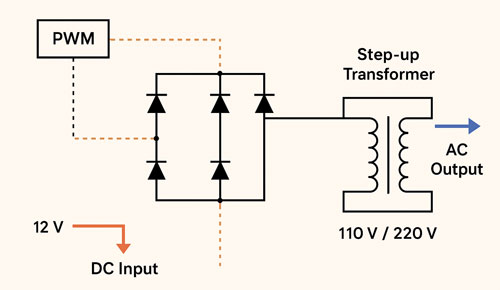
The principle of a pure sine wave inverter is to convert DC power from a battery into AC power similar to household mains electricity. This process involves three key steps: first, DC is converted into a high-frequency AC signal using Pulse Width Modulation (PWM); next, the low battery voltage (such as 12V or 24V) is boosted to 110V or 220V through a transformer; and finally, the output waveform is smoothed with LC filters to produce a clean and stable sine wave.
2. Components
To make a pure sine wave inverter, gather the following parts:
- Signal Generator
- Power Module / Power Semiconductor
- Driver / Controller
- Step-up Transformer / Power Transformer
- Filter / LC Components
- Battery Inverter / UPS Power Supply
- Protector / Circuit Breaker
3. Step-by-Step Process
Step 1: Generate PWM Signals
The foundation of a pure sine wave inverter begins with generating precise control signals. This is achieved using a Driver / Controller programmed to produce SPWM (Sinusoidal Pulse Width Modulation). Unlike simple square pulses, SPWM varies the pulse width in proportion to a reference sine wave, which ensures that the final AC output resembles the smooth curve of utility power. In most pure sine wave inverter designs, the PWM frequency is set between 20 kHz and 50 kHz, keeping switching noise out of the audible range and ensuring efficient operation. By generating accurate SPWM signals, the pure sine wave inverter sets the stage for clean and stable AC output suitable for sensitive electronics.

Step 2: Build the H-Bridge and Step Up Voltage
Once the PWM signals are ready, the next step in a pure sine wave inverter is to drive the power stage using Power Module / Power Semiconductor devices arranged in an H-bridge configuration. These high-speed switches, controlled by the SPWM signals from the Driver / Controller, rapidly chop the DC input into an alternating waveform. However, the voltage at this stage is still at the battery level, such as 12V or 24V, which is insufficient for powering household appliances. To solve this, the output is fed into a Step-up Transformer / Power Transformer that boosts the voltage to 110V or 220V AC, depending on regional standards. This stage is crucial because it not only increases the voltage but also ensures that the pure sine wave inverter can provide power levels equivalent to grid electricity.
Step 3: Apply Waveform Filtering
Even after voltage step-up, the output from the H-bridge and transformer is not yet a clean sine wave. Instead, it still contains switching harmonics from the SPWM process. To refine this signal, a low-pass Filter / LC Components (consisting of inductors and capacitors) is applied. This filter removes high-frequency components, leaving behind a smooth sinusoidal waveform. The quality of the filtering stage directly affects the performance of the pure sine wave inverter, as poor filtering can result in distortion, noise, or inefficiency. A well-designed LC filter ensures that the inverter produces a pure, grid-like sine wave capable of safely running sensitive devices such as medical equipment, laptops, or precision instruments.
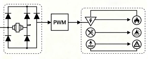
Step 4: Add Feedback and Protection
The next step in building a pure sine wave inverter is implementing a reliable feedback and protection system. Feedback circuits continuously monitor the output voltage and adjust the PWM duty cycle to maintain a stable sine wave under varying load conditions. Protector / Circuit Breaker features are equally important—these include safeguards against over-voltage, under-voltage, overload, overheating, and short circuits. Without these protections, the pure sine wave inverter risks damaging both itself and the devices it powers. By integrating feedback loops and robust protection mechanisms, the inverter becomes not only efficient but also safe, ensuring long-term reliability for household or industrial use.
Step 5: Testing and Calibration
The final stage in creating a pure sine wave inverter is thorough testing and calibration. Begin by connecting a small resistive load, such as a light bulb, to safely observe the inverter’s performance. Using an oscilloscope, check the waveform at the output to verify that it is a clean sine wave with minimal distortion. If necessary, fine-tune the SPWM parameters, transformer turns ratio, and Filter / LC Components values to achieve optimal results. Gradually test with larger and more complex loads, such as fans, laptops, or household appliances, to confirm that the pure sine wave inverter maintains stable voltage and frequency under different operating conditions. Proper calibration ensures that the inverter delivers reliable, grid-like power and can be trusted for long-term use in real-world applications.
4. Conclusion
Making a pure sine wave inverter may seem complex, but by breaking it into clear steps—PWM signal generation, voltage step-up, waveform filtering, feedback and protection, and finally testing and calibration—you can create an inverter that produces clean, reliable AC power. Unlike modified sine wave inverters, a pure sine wave inverter delivers electricity that closely matches grid standards, ensuring compatibility with even the most sensitive devices. With careful design, proper safety measures, and fine-tuning, your pure sine wave inverter can serve as a dependable power solution for both home and industrial needs.
5. Common Applications of Pure Sine Wave Inverters
A well-designed pure sine wave inverter is versatile and widely used in scenarios where clean and stable power is essential:
- Home Backup Power: Keeping lights, refrigerators, and essential appliances running during outages.
- Solar Energy Systems: Converting DC from solar panels or batteries into usable AC electricity.
- Medical Equipment: Powering sensitive devices that require stable and noise-free electricity.
- Communication Systems: Ensuring stable operation of radios, servers, and networking equipment.
- Mobile and Off-Grid Solutions: Providing reliable AC power in RVs, boats, and remote work sites.
Whether for daily use, emergency backup, or renewable energy systems, a pure sine wave inverter is a practical investment in stable, safe, and efficient power. For further technical support and professional consultation, please feel free to contact the ATO online store.
