How to Use PLC Pulse to Control Mode of Servo Motor?
The position control mode of the servo motor is very common in the precision movement of industrial automation. The principle is that the servo motor drive carries out precise control of the motor movement after receiving the position pulse and direction pulse of the pulse generator (PLC, single chip microcomputer). Servo motor has three control modes: speed control, position control and torque control. This time we will introduce the position control mode of ATO new servo motor, using PLC to pulse.
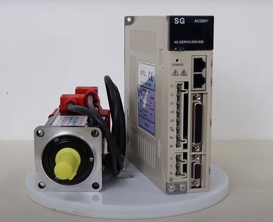
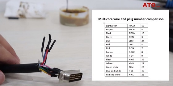
This is the ATO 200W servo motor kit. The CN3 interface is a custom control interface that is paired with a 42pin plug. We can weld multi-core wires to the 42pin plug as required. 200 watt servo motor with brushless design, 220V AC single or three-phase input. It is widely used in industrial automation, CNC machine, printing machinery and other fields.
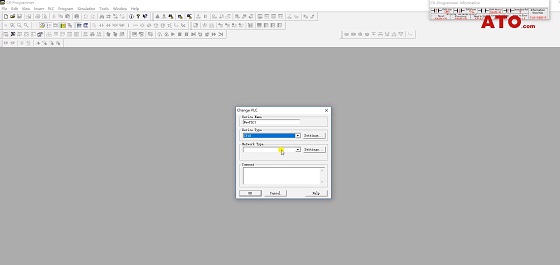
Position the required components and connect the circuit, and then follow the JOG test mode. After the completion of the test, began the establishment of PLC pulse program. Create a PLC program and select the PLC model.
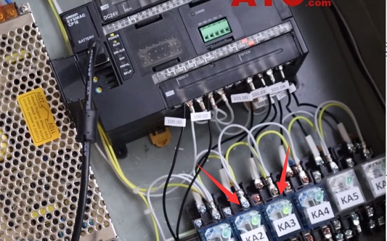
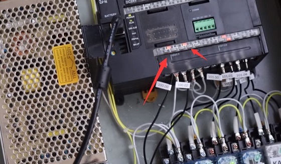
We use OMron PLC, servo motor drive pulse signal and direction pulse signal from its high-speed pulse interface 100.00 and 100.02, after entering 2kΩ resistance to reach the servo drive. The reason why 2kΩ resistance is used between PLC and driver is that the pulse voltage sent by PLC is 24V, and the pulse receiving voltage of the driver is specified as 5V. This kind of situation also occurs in the stepping motor drive pulse reception, so when we use servo drive or step drive, we should pay special attention to understand the maximum voltage that pulse receiving port can receive.
There are five instructions:
- The first instruction, the store data D100 reset immediately. Transfer hex 0000 to D100.
- The second instruction, the frequency parameter #2710 is transmitted to D100.
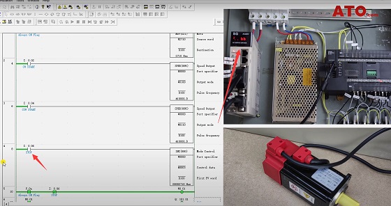
- The third instruction, rotate the SPEED instruction clockwise.
- The fourth instruction, rotate the SPEED instruction counterclockwise.
- The fifth instruction, stop the command INI (interrupt command).
The next instruction is relay control instruction, KA2 and KA3 are powered on by default. Connect the computer with PLC and transfer the program to PLC. PLC controls KA2 and KA3. By default, they are connected when powered on. KA2 and KA3 indicators are on.
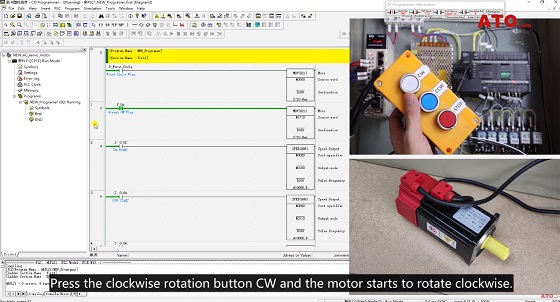
Press the clockwise rotation button CW and the motor starts to rotate clockwise. You can see the pulse output port of PLC 100.00 and direction control port 100.02 indicator light.
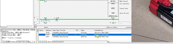
We can check the storage status of the PLC. D100 stores the current running frequency parameter. The larger the parameter value, the faster the motor speed. A276 and A277 store the current number of pulse transmissions.
Press the STOP self-locking button, all PLC output is stopped, the controller shows pot and not no signal input. When the STOP button is restored, we press the CCW button and the motor starts to reverse.

The pulse output port 100.00 indicator lights up. Stop the output, disconnect the controller enable, and control is complete.
The following video is a detailed description of servo motor PLC pulse control.
