Servo Motor: Types, Performance & Test Introduction
Servo motors are mainly classified into DC servo motors and AC servo motors. DC servo motors are divided into brush and brushless motors. Brushed motors have low cost, simple structure, large starting torque, wide speed range, easy to control and maintain (changing carbon brushes), it will generate electromagnetic interference and have specific requirements for the environment. Therefore, it is suitable for common industrial and civil occasions that are sensitive to cost.
In terms of structure, brushless motor and brush motor have similarities, also have rotor and stator, but brush motor and the structure of the opposite. The rotor of a brush motor is a coil winding, connected to the power output shaft, and the stator is a permanent magnet steel. The rotor of the brushless motor is permanent magnet steel, which is connected to the output shaft together with the housing, and the stator is the winding coil.
The brushless servo motor is small in size, light in weight, large in output, fast in response, high in speed, small inertia, smooth in rotation, and stable in torque. The control is complex and easy to realize intelligence, and its electronic commutation method is flexible, and it can be square wave commutation or sine wave commutation. The motor is maintenance-free, highly efficient, low operating temperature, low electromagnetic radiation, long life, and can be used in various environments.
Types of Servo Motors
AC servo motors
AC servo motors are also brushless motors, which are divided into synchronous and asynchronous motors. At present, synchronous motors are generally used in motion control. They have a large power range and can achieve great power. Large inertia, low maximum rotation speed, and rapid decrease as the power increases. Therefore, it is suitable for low-speed and smooth-running machines.
The structure of AC servo motor can be divided into two parts, namely stator part and rotor part. The stator structure is basically the same as that of the rotary transformer, and the two phase windings with 90 degrees of electric angle are placed in the stator core. One group is the exciting winding and the other group is the control winding. AC servo motor is a two-phase AC motor.
DC servo motors
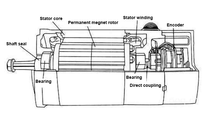
DC servo motor, which includes stator, rotor core, motor rotating shaft, servo motor winding commutator, servo motor winding, speed motor winding, speed motor commutator, all rotor core is made of silicon steel punching sheet laminated press fixed on the motor rotating shaft.
The motor which is used as a DC servo motor generally have a separate DC source in the field of winding and armature winding. Control can be archived by controlling the armature current or the field current. Depending on the application, the control shall be applied to the DC servo motor. Due to low armature inductance, dc servo motors provide very accurate and fast response to start or stop command signals. DC servo motors are used in similar equipment and computer numerical control machines. Actuators in various digital control systems. Power drives that require precise control of constant speed or require precise control of speed change curves.
RC servo motors
RC servo motor refers to the engine that controls the operation of mechanical components in the servo system, and is an indirect variable speed device for auxiliary motors. RC servo motors can accurately control speed and position accuracy, and can also convert voltage signals into torque and speed to drive control objects. Servo motor rotor speed is controlled by the input signal, and can respond quickly. In the automatic control system, RC servo motor used as an executive element, and has the characteristics of small electromechanical time constant, high linearity, starting voltage, can convert the electrical signals received into the angular displacement or angular velocity output on the motor shaft. When the signal voltage is zero, there is no rotation phenomenon, and the speed decreases uniformly with the increase of torque.
Linear servo motors
Linear servo motor is a kind of motor similar to position rotation servo motor. But it has additional mechanisms to change the output back and forth from the direction of the circle. The working principle likes torque motors, but they are turned on and pushed flat. Electrical energy is converted into linear mechanical energy with high efficiency through electromagnetic interaction between coil assembly (main part) and permanent magnet assembly (minor part). Other common names for major components are motor, moving part, slide or slide, while minor components are also called magnetic circuits or tracks.
Because the linear servo motor is designed to generate high force at low speed or static, dimensions are not based on power but purely on force, as opposed to conventional drives. The moving part of a linear servo motor is directly coupled to the machine load, which saves space, simplifies the machine design, eliminates backlash and eliminates potential fault sources. Such as ball screw system, coupling, belt, or other mechanical transmission.
Gear servo motors
Gear servo motor is a kind of motor which can produce high torque when the low speed motor output. This type of motors are used in many different applications and are commonly found in homes and workplaces. A gear servo motor can run on either AC or DC motors. The output range of a gear motor can be between 1200 and 3600 revolutions per minute or RPM.
The purpose of the gearbox is to reduce the speed and thus produce a different torque at the end of the shaft. Torsional stiffness is the torsional resistance generated when torque is applied to motor shaft, transmission element and load. An infinitely rigid system can transfer torque to the load without angular deflection around the axis of rotation. However, even the strongest steel shafts can warp slightly under heavy load. The deflection varies with the applied torque, the material of the transmission element and its shape. It makes intuitive sense that long, thin parts are more flexible than short, thick ones. This resistance to torsion is how helical springs work, because compression produces a slight twist in each turn of the spring. When torsional stiffness is not infinite, the system behaves like a spring, which means that potential energy is stored in the system while the load resists torsion.
Advantages of Servo Motors
- Precision: It realizes the closed-loop control of position, speed and torque; overcomes the problem of stepper motor out-of-step;
- Rotation speed: Good high-speed performance, generally rated speed can reach 2000-3000 rpm;
- Adaptability: Strong anti-overload capability, able to withstand a load of three times of the rated torque, which is especially suitable for occasions with instantaneous load fluctuations and requirements for fast starting;
- Stable: Stable operation at low speed, it won't occur stepping operation phenomenon as stepping motor when running at low speed. Suitable for occasions with high-speed response requirements;
- Timeliness: The dynamic response time of motor acceleration and deceleration is short, generally within tens of milliseconds;
- Comfort: Heat and noise are significantly reduced.
Performance Comparison of Stepper Motor and AC Servo Motor
As an open-loop control system, stepper motor has an essential connection with modern digital control technology. In the current domestic digital control system, stepper motors are widely used. With the advent of all-digital AC servo systems, AC servo motors are increasingly used in digital control systems. In order to adapt to the development trend of digital control, most of the motion control systems use stepper motors or all-digital AC servo motors as executive motors. Although the two are similar in control mode (pulse train and direction signal), there are big differences in performance and applications. Now make a comparison of the performance of them
Different control accuracy
The step angle of the two-phase hybrid stepper motor is generally 1.8°, 0.9°, and the step angle of the five-phase hybrid stepping motor is generally 0.72°, 0.36°. There are also some high-performance stepping motors with a smaller step angle after subdividing. The control accuracy of the AC servo motor is determined by the rotary encoder at the back of the motor shaft.
Different low frequency characteristics
Stepper motors are prone to low-frequency vibration at low speeds. The vibration frequency is related to the load condition and the performance of the drive. It is generally considered that the vibration frequency is half of the no-load take-off frequency of the motor. This low-frequency vibration phenomenon determined by the working principle of the stepper motor is harmful to the normal operation of the machine. When stepping motors work at low speeds, damping technology should generally be used to overcome low-frequency vibration phenomena, such as adding a damper to the motor, or using subdivision technology on the drive.
The AC servo motor runs very smoothly, and there is no vibration even at low speeds. The AC servo system has a resonance suppression function, which can cover the lack of rigidity of the machine, and the internal frequency analysis function (FFT) of the system can detect the resonance point of the machine, which is convenient for system adjustment.
Different moment frequency characteristics
The output torque of a stepping motor decreases with the increase of the speed, and will drop sharply at a higher speed, so its maximum working speed is generally 300-600RPM. The AC servo motor has a constant torque output, that is, it can output a rated torque within its rated speed (generally 2000RPM or 3000RPM), and a constant power output above the rated speed.
Different the overload capacity
Stepper motors generally do not have overload capacity. AC servo motors have strong overload capacity. They are speed overload and torque overload capacity. Its maximum torque is two to three times the rated torque, which can be used to overcome the moment of inertia of the inertial load at the moment of starting. Because stepper motors do not have this overload capacity, in order to overcome this moment of inertia when selecting a model, it is often necessary to select a motor with a larger torque, and the machine does not need such a large torque during normal operation, so a torque appears. The phenomenon of waste.
Different operating performance
The stepping motor is controlled by open loop control. If the starting frequency is too high or the load is too large, it is easy to lose steps or stall. When the speed is too high, it is easy to overshoot. Therefore, in order to ensure its control accuracy, it should be handled well. Speed up and down issues. The AC servo drive system is a closed-loop control. The drive can directly sample the feedback signal of the motor encoder. The position loop and speed loop are formed inside. Generally, the stepper motor will not lose steps or overshoot, and the control performance is more reliable.
Different speed response performance
It takes 200 to 400 milliseconds for a stepping motor to accelerate from a standstill to a working speed (generally several hundred revolutions per minute). The AC servo system has better acceleration performance. It only takes a few milliseconds to accelerate from a standstill to its rated speed of 3000RPM. It can be used in control situations that require fast start and stop.
In summary, the AC servo system is superior to stepper motors in many aspects of performance. However, stepper motors are often used as executive motors in less demanding occasions. Therefore, in the design process of the control system, various factors such as control requirements and cost should be considered comprehensively, and an appropriate control motor should be selected.
How to Test a Servo Motor?
1. Initialization parameters
Before wiring, initialize the parameters first.
The servo motor is on the control card: Select the control mode, clear the PID parameters, let the default enable signal turn off when the control card is powered on, save this state to ensure that the control card is in this state when it is powered on again.
On the servo motor: Set the control mode, set the enable to be controlled by the outside, set the gear ratio of the encoder signal output, then set the proportional relationship between the control signal and the motor speed. Generally speaking, it is recommended that the maximum design speed in servo work corresponds to a control voltage of 9V. For example, sets the speed corresponding to 1V voltage, and the factory value is 500. If you only plan to make the motor work below 1000 rpm, then set this parameter to 111.
 2. Wiring
Power off the control card and connect the signal line between the control card and the servo. The following lines must be connected: the analog output line of the control card, the enable signal line, and the encoder signal line of the servo output. After rechecking that there is no error in the wiring, the motor and control card (and PC) are powered on. At this time, the motor should not move, and it can be easily rotated with external force. If this is not the case, check the setting and wiring of the enable signal. Rotate the motor with external force and check whether the control card can correctly detect the change of the motor position, otherwise check the wiring and setting of the encoder signal.
3. Try direction
For a closed-loop control system, if the direction of the feedback signal is incorrect, the consequences must be catastrophic. Turn on the enable signal of the servo through the control card. This is the servo should rotate at a lower speed, which is the legendary "zero drift". Generally, there will be instructions or parameters to suppress zero drift on the control card. Use this command or parameter to see if the motor speed and direction can be controlled by this command (parameter). If it cannot be controlled, check the analog wiring and the parameter settings of the control mode. Confirm that a positive number is given, the motor rotates forward, and the encoder count increases; when a negative number is given, the motor rotates reversely, and the encoder count decreases. If the motor carries a load and the stroke is limited, do not use this method. Do not give too much voltage to the test, it is recommended to be below 1V. If the directions are inconsistent, you can modify the parameters on the control card or the motor to make them consistent.
4. Suppress zero drift
In the closed-loop control process, the existence of zero drift will have a certain impact on the control effect, and it is best to suppress it. Use control card or servo to suppress zero drift parameters, carefully adjust to make the motor speed approach zero. Since the zero drift itself has a certain degree of randomness, it is not necessary to require the motor speed to be absolutely zero.
5. Establish closed-loop control
Let go of the servo enable signal through the control card again, and enter a smaller proportional gain on the control card. As for how big it is, it can only be based on feeling. If you are not at ease, enter the smallest allowable value of the control card. value. Turn on the enable signal of the control card and servo. At this time, the motor should be able to roughly act according to the motion command.
6. Adjust closed-loop parameters
Fine-tuning the control parameters to ensure that the motor moves in accordance with the instructions of the control card is the work that must be done, and this part of the work is more of experience, which can only be omitted here.
