Compass Sensor FAQs
A compass sensor is a sensor used to measure and determine direction, helping users obtain the correct orientation for navigation and mapping. Compass sensors are used not only for navigation but also for a wide range of other functions, such as indoor positioning, autonomous control, and rotation.
Whether you're a drone developer, a robotics enthusiast, or a navigation systems engineer, choosing the right compass sensor (electronic compass) is crucial to project success. Confused by the myriad models and technical specifications, we've compiled this comprehensive FAQ guide, covering basic concepts to advanced applications, to answer all your questions, from product selection to purchasing, helping you make the most informed decision.
Contents
Q1: How does a compass sensor work?
Q2: What projects are suitable for using a compass sensor?
Q3: What are the most critical factors when selecting a compass sensor?
Q4: What is tilt compensation? Why is it so important?
Q5: What do soft-iron and hard-iron compensation mean in compass sensors?
Q6: How do I calibrate the compass sensor after installation?

Q1: How does a compass sensor work?
A compass sensor uses the subtle effects of magnetic fields on internal electrical currents (e.g., changes in resistance) to measure the strength of the Earth's magnetic field in various directions, thereby calculating the device's heading. Its core principle is to measure the Earth's magnetic field, a "vector." The sensor contains three mutually perpendicular probes that measure magnetic field strength in the X, Y, and Z directions. When the device is level, it uses the trigonometric function atan2(Y, X) to directly calculate the heading angle using the X and Y axis values. When the device is tilted, it combines the accelerometer data with mathematical calculations to convert the magnetic field data to a horizontal plane before calculating the heading. This process is called tilt compensation.
Q2: What projects are suitable for using a compass sensor?
Any project that requires knowing "absolute direction" rather than just "rotation" is suitable for a compass sensor. "Absolute direction" here refers to the direction relative to the geographic North Pole, which is the direction indicated by a traditional compass. The following are some typical and common project categories for you to choose from:
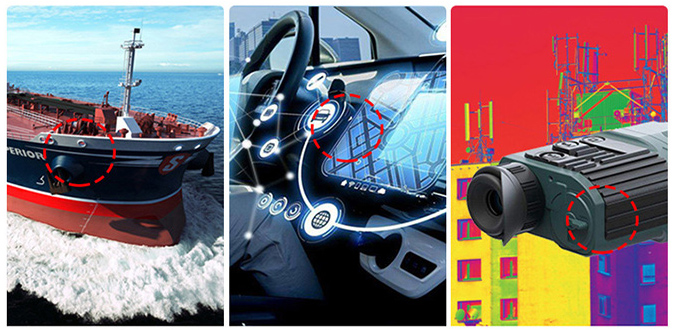
Navigation and Positioning
This is a classic application area. Compass sensors are crucial when GPS fails to provide direction or requires assistance.
- Drones/Unmanned Vehicles: Enable autonomous cruising, course lock, and automatic return-to-home. GPS provides location, but cannot accurately determine the nose direction when hovering or at low speeds, necessitating a compass.
- Robotics: Used for efficient path planning in sweeping robots, straight-line tilling by agricultural robots, and navigation systems for other autonomous mobile robots.
- Vehicle and Ship Navigation: Provides real-time heading information for vehicle or ship systems, supplementing and backing up GPS signals.
Pose Determination and Orientation
Projects in this category require determining the device's orientation in space.
- Smartphones and tablets: These enable map apps to rotate with orientation, AR applications to keep virtual objects fixed to real-world orientation, and simple compass functionality. It is a core component of smartphones, supporting map navigation, AR games, photo geotagging and other functions.
- VR/AR headsets and controllers: These track the user's head rotation and the orientation of the controller, serving as one of the core sensors for an immersive experience.
- Remote controls and game controllers: These, like the Wii Remote or some advanced remotes, allow users to control an on-screen cursor or direction by moving and pointing.
- Surveying and Exploration Equipment: These are used in specialized fields such as measuring azimuth and map orientation.
IoT and Smart Devices
These projects use direction sensing to enable smarter interactions and controls.
- Smart Home: Examples include smart curtains and solar panels. Smart curtains automatically open and close based on the sun's direction to adjust indoor light and temperature. Compass sensors allow solar panels to automatically track the sun to maximize energy collection efficiency.
- Outdoor IoT Devices: Used for directional calibration of field monitoring equipment (such as weather stations) to ensure sensors are pointing correctly.
Q3: What are the most critical factors when selecting a compass sensor?
Accuracy and stability
These are the most critical indicators, directly determining the reliability of the final product.
- Heading accuracy: Usually measured in degrees (e.g., ±0.5°, ±1.0°). The lower the value, the better.
- Repeatability: Are the results consistent when taking multiple measurements at the same location? High repeatability is sometimes more practical than simply high nominal accuracy.
- Sensitivity: The smallest magnetic field change a sensor can detect. The higher the sensitivity, the more responsive it is to even subtle changes in the Earth's magnetic field.
Magnetic Interference Compensation Capability
Does the sensor provide advanced calibration algorithms (such as ellipsoid fitting) to compensate for hard-iron and soft-iron interference?
Hard-iron interference arises from permanent magnets or magnetized components within the device (such as speakers and motors), which produce a constant magnetic field offset. Soft-iron interference arises from external magnetic fields magnetizing ferromagnetic materials within the device (such as metal casings and screws), and this interference varies with direction.
System Integration and Ease of Use
This affects your development difficulty and time cost.
- Communication Interface: I2C or SPI? I2C is simple and uses fewer MCU pins, but it's slower. SPI is extremely fast and has good interference immunity, but requires more wiring.
- Built-in Sensor Fusion: Advanced modules have a built-in processor that directly outputs a filtered and fused stabilized heading angle or quaternion.
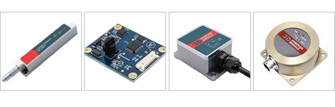
A variety of high-precision electronic compass sensors for selection at the ATO Industrial Automation online shop is also offered. These include two-dimensional and three-dimensional electronic compass sensors. These compass sensors feature industrial-grade designs, electromagnetic interference resistance, and advanced hard and soft magnetic calibration algorithms. Here you can choose products that will satisfy you.
Q4: What is tilt compensation? Why is it so important?
Tilt compensation is a technology that combines data from the accelerometer with the compass sensor (magnetometer) to correct and calculate the correct heading angle when the compass sensor (magnetometer) is not level. The magnetometer measures the magnetic field strength along its own coordinate system (X, Y, and Z axes). When the device is tilted, the magnetometer's coordinate system also tilts. The X and Y axis data it measures are no longer purely horizontal; a portion of the vertical (Z-axis) magnetic field is mixed in. The accelerometer accurately measures the direction of gravity, allowing it to calculate the device's pitch and roll angles relative to the horizontal plane. Using these two angles, a mathematical formula (rotation matrix) is used to "convert" the tilted magnetic field data back to the horizontal plane. The converted X and Y components, on a "virtual horizontal plane," are used to calculate the accurate heading angle.
Tilt compensation is crucial because, without it, compass readings would be completely inaccurate and unusable in most practical applications. When the device is perfectly level, the heading angle calculation formula (heading angle = atan²(Y, X)) is accurate. However, this simple calculation breaks down once the device is tilted. A tilt of just 10° can produce a heading error of more than 10°; at a 45° tilt, the error can reach tens of degrees, rendering the reading meaningless. Tilt compensation is the key technology that transforms electronic compasses from "laboratory toys" into "practical tools." By fusing data from magnetometers and accelerometers, it addresses the fundamental issue of a device's changing posture in the real three-dimensional world. Therefore, when choosing a compass sensor, unless your device can always be absolutely level (which is almost impossible), you must select a sensor or module with tilt compensation (typically an IMU with integrated magnetometers and accelerometers).
Q5: What do soft-iron and hard-iron compensation mean in compass sensors?
What is hard iron interference?
First, hard-iron interference arises from permanent magnets or magnetized hard magnetic materials (such as screws, motor housings, and speakers) within or near the device. It generates an additional magnetic field with constant strength and fixed direction. Regardless of device rotation, this interfering magnetic field vector acts as if "stuck" to the device, always pointing in the same direction. So how does hard-iron compensation work? Because hard-iron interference is a constant offset, compensating for it is relatively simple. Through calibration (for example, by slowly rotating the device one revolution on a horizontal plane), the system can measure the X, Y, and Z components of this constant offset. For all subsequent readings, simply subtract this fixed offset from the original measurement.
What is soft-iron interference?
Soft-iron interference originates from soft magnetic materials within a device (such as iron casings and iron components on PCBs). These materials are inherently nonmagnetic, but are easily magnetized by external magnetic fields (including the Earth's magnetic field and hard-iron interference fields), becoming a secondary magnetic source themselves. This is the most complex and challenging interference to address. The strength and direction of the magnetization of soft-iron materials changes with the device's orientation relative to the Earth's magnetic field. This distorts the original magnetic field. It's like a musician listening to music in an irregularly shaped sound gallery. The walls (soft-iron materials) distort and reflect the sound (the Earth's magnetic field), causing the original music to be distorted. This distortion also changes as you move around.
So how does soft-iron compensation work? The soft-iron effect can be thought of as scaling, stretching, and shearing the original magnetic field vector. Mathematically, it's equivalent to multiplying the original geomagnetic field vector by a 3x3 matrix (transformation matrix).
Soft-iron compensation requires more complex calibration (for example, performing a figure-eight or spherical rotation in three-dimensional space) and collecting magnetic field data at a large number of different attitudes. In an interference-free environment, these data points should be distributed on a sphere centered at the origin. However, in the presence of soft-iron interference, they are distributed on an ellipsoid that is offset from the origin. The compensation process uses an algorithm to determine how this "sphere" is distorted into an "ellipsoid" and calculate the inverse transformation matrix to "correct" the ellipsoid back to a sphere. The ATO online store sells electronic compass sensors with hard-magnetic, soft-magnetic, and tilt-compensated functions, providing calibrated, high-precision measurements. Using a central processor to calculate heading in real time and a three-axis accelerometer to compensate for tilt, they provide precise heading data even in the most challenging environments.
Q6: How do I calibrate the compass sensor after installation?
The complexity of the calibration process depends on the sensor and algorithm. Calibration for most consumer-grade modules is straightforward, typically requiring only a slow 360° rotation of the device in the horizontal plane (for models with tilt compensation, a figure-eight flip may also be required). The sensor automatically records the magnetic field extremes in all directions to complete the calibration. Development kits typically include sample code for one-click calibration.
