What is a Compass Sensor?
A compass sensor, commonly referred to in modern technology as an electronic compass or magnetometer, is a precision electronic component that detects the direction of the Earth's magnetic field and determines the relative orientation of a device. While it shares a common heritage with the compass, one of the Four Great Inventions of Ancient China, its technological essence has undergone revolutionary changes.
While traditional compasses rely on the physical deflection of a magnetic needle in response to the Earth's magnetic field to indicate direction, modern compass sensors convert magnetic field signals into electrical signals, which are then processed through complex algorithms to output digital direction information. This represents a quantum leap from mechanical indication to electronic sensing.
Contents
- History of Compass Sensor Development
- How a Compass Sensor Works
- Compass Sensor Types
- Applications of Compass Sensors
- Future Development of Compass Sensors
History of Compass Sensor Development
From a technological perspective, the development of compass sensors has undergone several significant stages. The earliest sensors, based on the Hall effect principle, determined direction by measuring the potential difference caused by changes in the magnetic field.
With advances in materials science, anisotropic magnetoresistive (AMR) sensors have become mainstream. These sensors exploit the property of specialized materials where the resistance changes with the direction of the magnetic field, significantly improving measurement accuracy. Today's most advanced compass sensors are giant magnetoresistance (GMR) and tunnel magnetoresistance (TMR). These nanoscale technologies can detect minute magnetic field changes with sensitivity hundreds of times greater than traditional devices.
Modern compass sensors typically consist of three perpendicular magnetoresistive elements, capable of simultaneously measuring magnetic field strength in the X, Y, and Z axes, enabling complete three-dimensional magnetic field mapping.
How a Compass Sensor Works
Compass Sensor Operation
The operation of a compass sensor is a sophisticated, multi-step process.
Step 1: The sensor collects raw magnetic field data, which not only contains information about the Earth's magnetic field but is also affected by various interfering magnetic fields.
Step 2: A dedicated signal processing chip performs pre-processing, including temperature compensation and offset correction. Kalman filtering and other algorithms are then used to eliminate hard-iron interference (from the device's own permanent magnetic field) and soft-iron interference (from induced magnetic fields in the external environment).
Step 3: The processor combines this cleaned data with attitude information provided by the accelerometer and gyroscope through sensor fusion to calculate the device's precise azimuth relative to magnetic north. The output is accurate to 0.1 degrees.
Compass Sensor Accuracy
It is important to note that the accuracy of a compass sensor is affected by many factors. In addition to obvious sources of electromagnetic interference, temperature changes, mechanical stress, and even device aging can cause measurement errors. Therefore, high-end devices typically use a multi-sensor fusion solution, combining data sources such as GPS and visual odometry for cross-validation and compensation.
At the same time, user calibration procedures have become increasingly intelligent, evolving from manual "figure-eight" rotation calibration to the real-time background calibration feature now available on many devices, which continuously optimizes pointing accuracy without the user noticing.

Compass Sensor Types
Compass sensors can be categorized into two types based on their measurement dimensions (the dimensions of data they can provide).
2D compass sensors
Functional definition: A 2D compass sensor refers to sensors or sensor systems that only provide heading angles (Azimuth) in the horizontal plane.
Important prerequisite: This type of compass assumes the device is level (i.e., pitch and roll angles are zero). If the device is tilted, the readings will be significantly inaccurate and invalid.
Implementation: This is typically not a standalone sensor, but rather a system. It most commonly combines a single-axis (Z-axis) magnetic sensor and a dual-axis (X, Y-axis) accelerometer. The accelerometer detects whether the device is level and compensates for tilt. Therefore, a so-called "2D compass" may contain sensors with three physical axes (one magnetic + two accelerometers).
Features: Low cost, but limited in use (must be level). Often found in early electronic devices or simple electronic compasses.
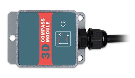
3D compass sensors
Functional definition: A 3D compass sensor refers to a sensor system that provides complete three-dimensional directional information, including heading, pitch, and roll, at any orientation (regardless of device tilt).
Implementation: This is essentially a sensor fusion system. Its core is a three-axis magnetometer, but it must also be combined with a three-axis accelerometer (to measure the gravity vector and calculate tilt) and typically a three-axis gyroscope (to provide dynamic angular velocity, making calculations smoother and more robust to interference). These three components are collectively known as an "Inertial Measurement Unit (IMU)" or "Attitude and Heading Reference System (AHRS)."
Features: Powerful and unrestricted (it can accurately point to north even when tilted), but the system is complex, costly, and the software algorithms are challenging. Modern devices such as smartphones and drones use this type of high-accuracy compass sensor system.
Applications of Compass Sensors
In practical applications, compass sensors have become the "eyes of direction" in the intelligent era.
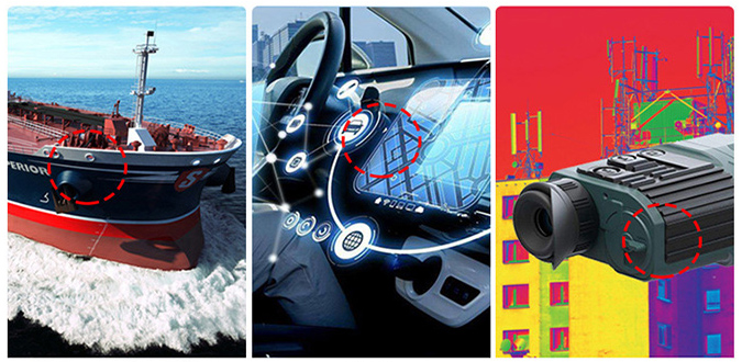
- The consumer electronics sector: They are a core component in smartphones that enable map navigation, AR gaming, photo geotagging, and other features.
- The transportation sector: They provide a continuous direction reference for in-vehicle navigation systems, complementing GPS.
- Aerospace: They provide a reliable heading reference for drones, satellites, and other aircraft.
- The military: They are used for precision direction-finding missions such as missile guidance and individual navigation.
- Scientific research: They are indispensable measurement tools for geological exploration, oceanographic surveys, and space exploration.
Notably, modern compass sensors are deeply integrated with artificial intelligence technology. Through machine learning algorithms, they can identify and adapt to specific interference environments, achieving self-learning and performance optimization.
Future Development of Compass Sensors
Looking ahead, compass sensors are developing towards higher accuracy, stronger interference resistance, and lower power consumption. Emerging technologies like the quantum compass are beginning to move from the laboratory to practical applications. This new sensor, based on atomic spin effects, is independent of the Earth's magnetic field and can provide precise orientation in environments beyond GPS coverage, such as underwater and underground. It represents the next generation of navigation technology. Furthermore, ATO.com learned that the trend toward miniaturization is enabling the integration of compass sensors into smaller wearable devices and IoT nodes, playing a vital role in smart cities, precision agriculture, and other fields.
The history of compass technology is a microcosm of human technological evolution. Today's compass sensors not only inherit the cultural mission of their ancestors to provide direction, but also, through digital and intelligent means, continue to provide an indispensable reference for human exploration and understanding of the universe.
